307A push-pull amp
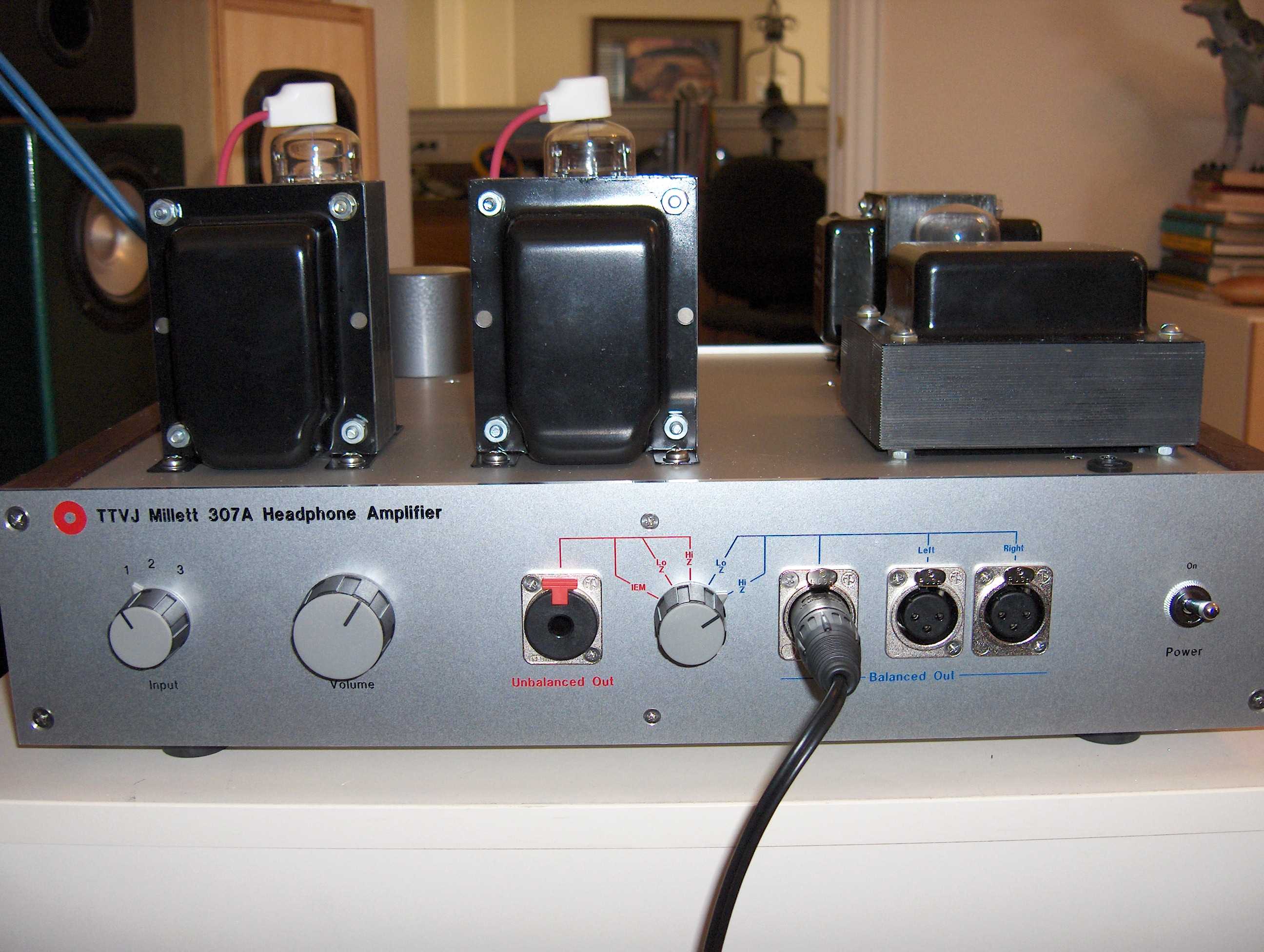
I've been playing with the 307A directly heated pentode for a while now. It's really one of my favorite tubes. I designed and build a (expensive) single-ended tube headphone amp using it, the TTVJ Millett 307A.
I've been breadboarding various SE and PP power amp circuits with the 307A for a good year or more, but just haven't had the time until now to come up with anything I like.
But first, a little about the 307A:
As far as I can tell, the 307A was only used in a WWII US army field radio. Even though the only datasheet I can find is from Western Electric, I've never actually seen a WE branded 307A (and I have a pretty good collection of them). I have 307A's from Ken-Rad (the most common), and Sylvania, Raytheon (AKA RK-75), and National Union. At least in the pictures the WE tube looks exactly like the Sylvania tube, so I'm guessing that WE may have just re-branded Sylvania tubes (or vice-versa).
Below are a series of photos of a Ken-Rad 307A tube in various stages of dismemberment. Click on the photos for full-sized images.
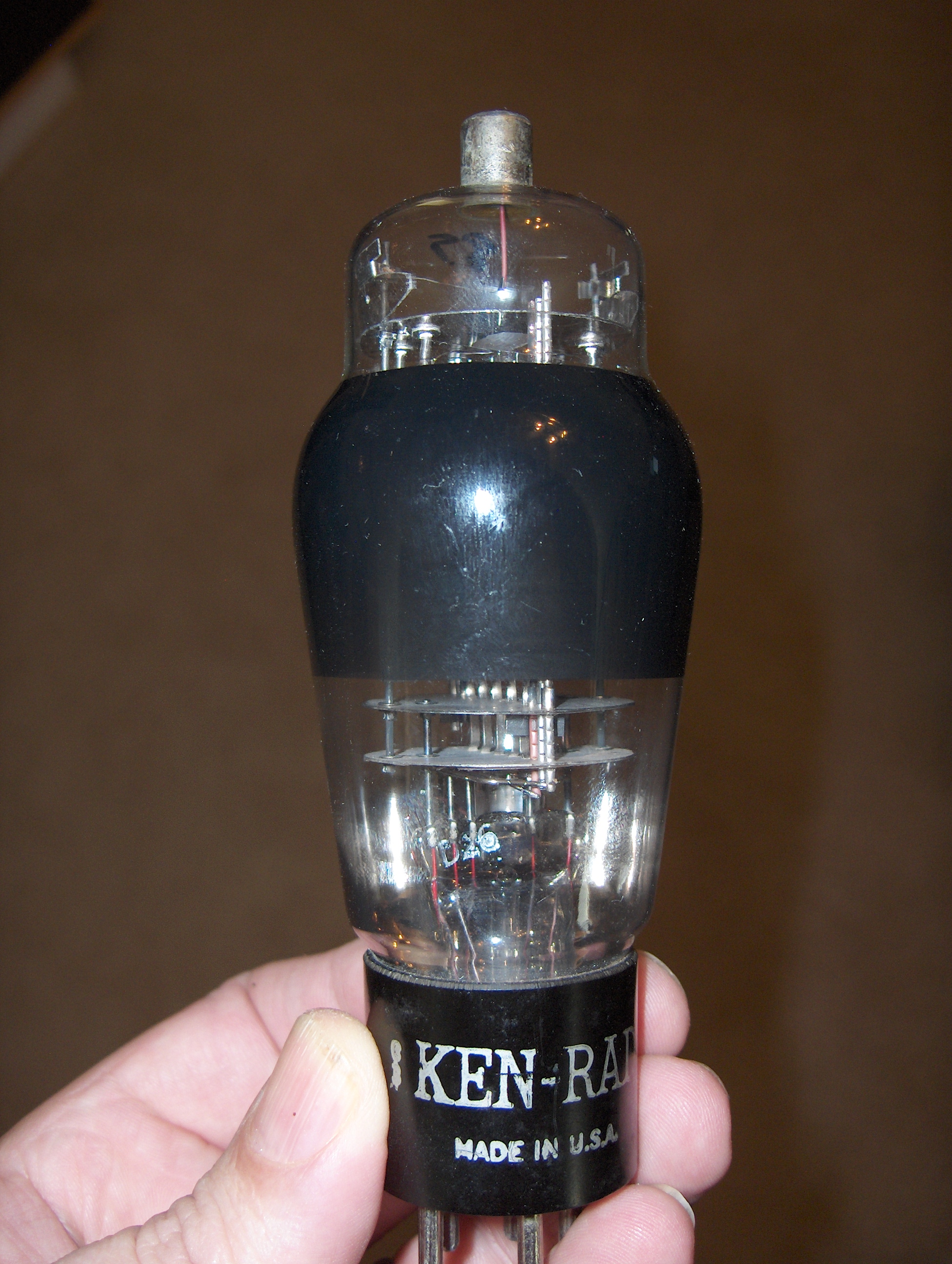
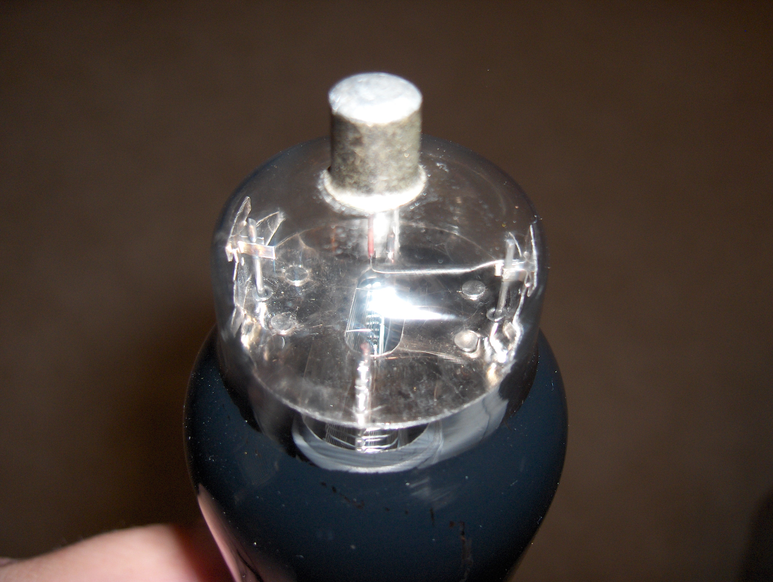
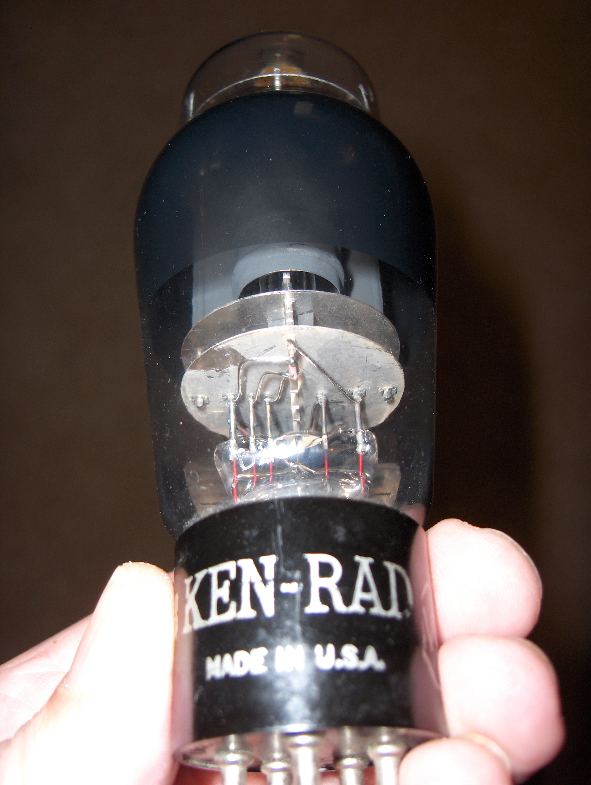
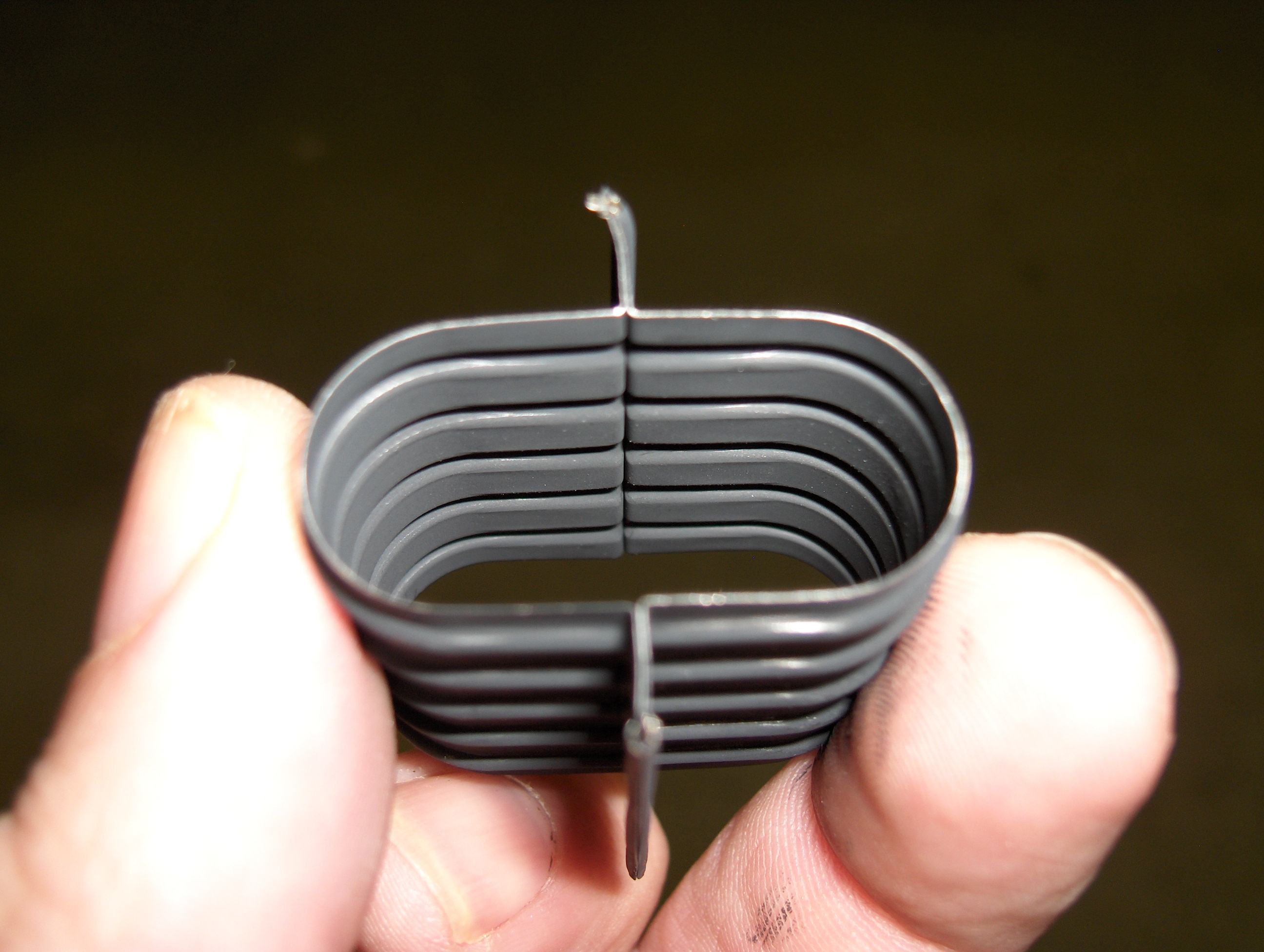
This is an old-fashioned pentode. No beam plates here... concentrically wound grids and an oval plate.
Finding 307A's can be a bit of a challenge. My stock came from England. I believe that most of the spares wound up in Europe since this is where the radio was deployed in the war. There are small quantities available at US tube dealers, and I know of at least one guy in Europe who seems to have a big stash.
Anyway, back to amplifiers... I have run the 307A in pentode, ultralinear, and triode mode. I have not been impressed with pentode or UL operation - it works fine but nothing to write home about. But triode connected - in this case by connection G2 AND G3 to the plate - you get a very nice triode, somewhere between a 2A3 and a 300B in characteristics.
I found some triode curves somewhere on the net. I'd like to credit whoever made these but I cannot figure out where they came from - if it was you, please let me know so I can ask permission (and forgiveness) to post it!
The plate dissipation rating is 10 watts, but that seems to be a very conservative rating. I've been running them right at or slightly above that point for some time with no problems.
Here is the circuit that I am currently breadboarding (for a more readable schematic download the PDF version here).
This design is pretty conventional. An input buffer drives a phase splitter transformer (I'm using a Sescom MI-19, which performs very well). A differential driver stage using 7W7 loktal pentodes drives the 307A grids via coupling capacitors. The 7W7 is a relatively unknown (until now?) jewel. I got a couple dozen for $1.00 each at RES!
A couple of oddities you might notice: The B+ is fed through a choke, and a capacitor (call it ultrapath or whatever you'd like) connected to the filament end of the cathode bias resistor. This B+ is used to feed the driver stages with no decoupling. So basically from an AC standpoint everything is tied to the 307A filaments. I found experimentally that this scheme resulted in significantly lower distortion than other connections. I believe that what's happening is that the B+ is being modulated with common-mode signal which tends to force balance in the entire circuit.
Another oddity is that the driver stage - a diff pair of 7W7 pentodes - share a common screen grid dropping resistor, and a very small (0.001uF) bypass capacitor. Again, experimentally, this worked considerably better than the usual choices, including a VR tube to regulate the screen supply, and separate screen dropping resistors, and using large bypass capacitor(s). Interestingly, using a big bypass cap increased THD significantly across the board. Adding a small cap lowered THD at high frequencies (above ~10kHz) without increasing distortion at low frequency.
The input stage uses a triode-connected 7W7 in a near-unity-gain plate follower configuration. I did this to remove any dependencies on the driving source impedance - the frequency response and THD at high frequency is very dependent on how you drive the phase splitter transformer. With the buffer, the input is high impedance (100k) and resistive, so the source impedance doesn't affect the amp performance. Almost any triode will work - a 6SN7 / 6J5 / 7N7 / 7A4 works fine, but the higher Gm of the 7W7 makes for incredibly flat frequency response.
Here is the power supply, which is entirely conventional:
You can drive the 307A filaments with AC - with a hum balance pot you can probably get it quiet enough. But even with this I measured lots of hum intermodulation, so I opted to go with DC filaments.
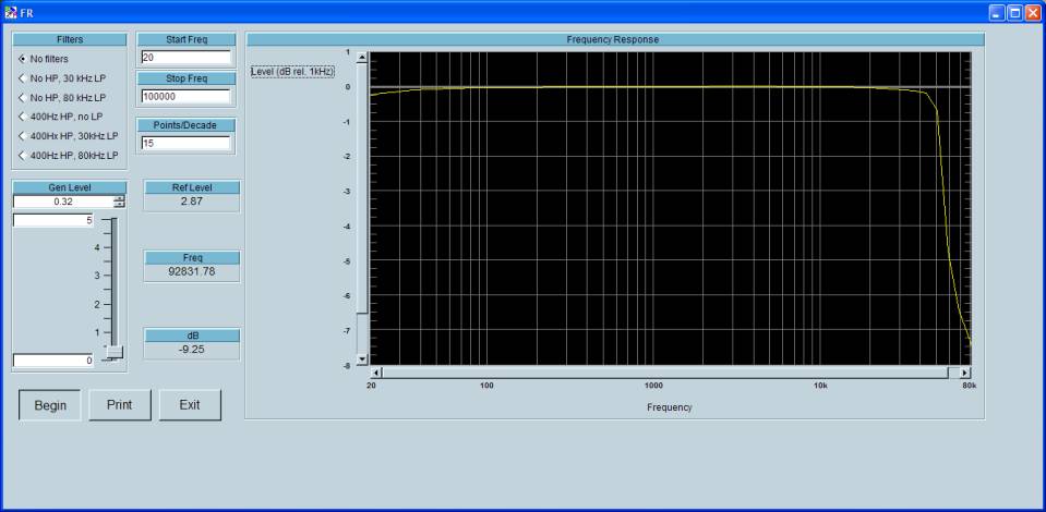
The performance of this amp is pretty impressive. Check out the frequency response (@ 1 watt out)...
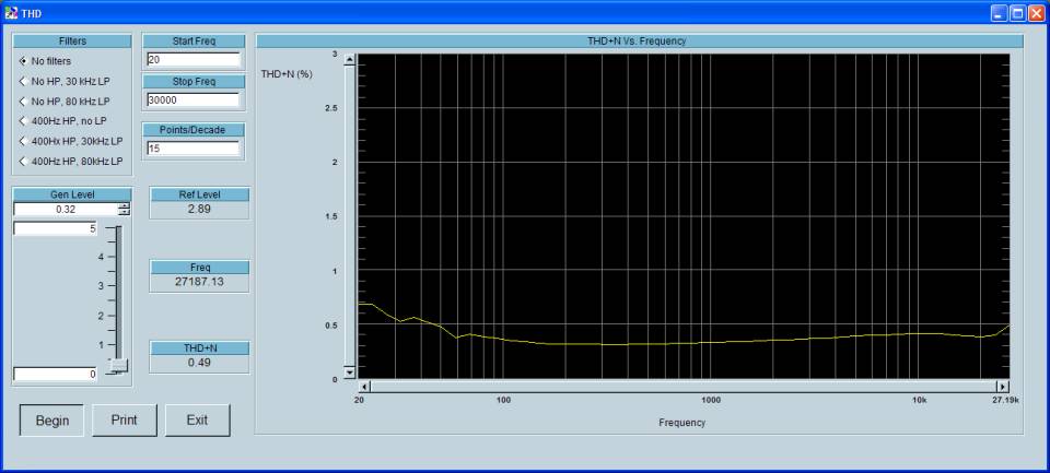
...the THD+N vs. Frequency at 1W out...
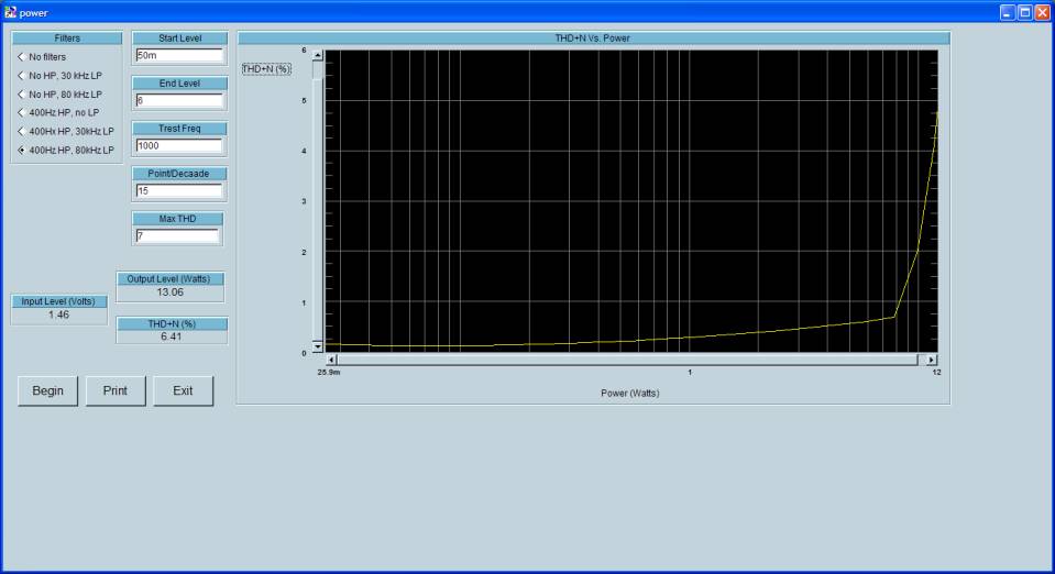
...and the THD+N vs. output power (@1kHz):
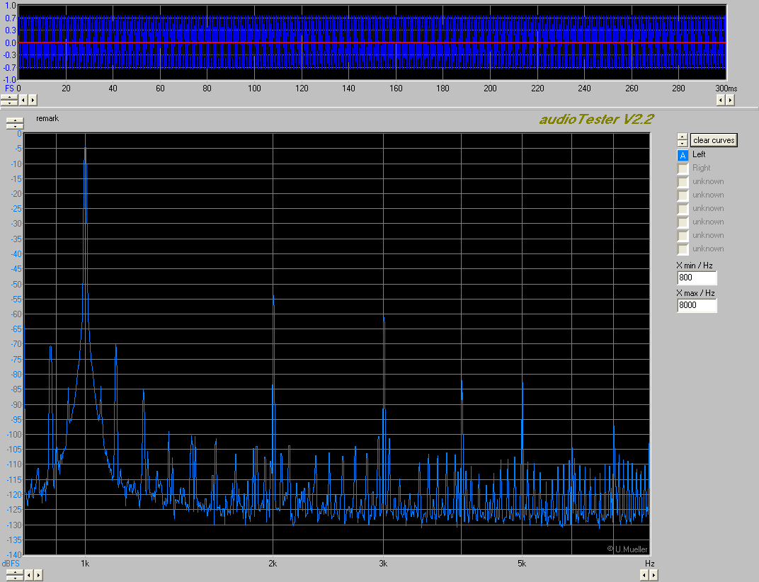
An FFT @ 1 watt shows a mix of distortion products Note there are still 60Hz products (albeit 70dB down). Not sure where this is coming from - DC on the7W7 heaters made no difference. This was powered from a regulated bench supply so I don't think it is B+ ripple. Maybe just a measurement artifact...
I haven't listened to this amp yet (I'm an engineer, damn it!). I do plan on building a proper stereo amp with this design, so listening will wait until then. More details to come then.