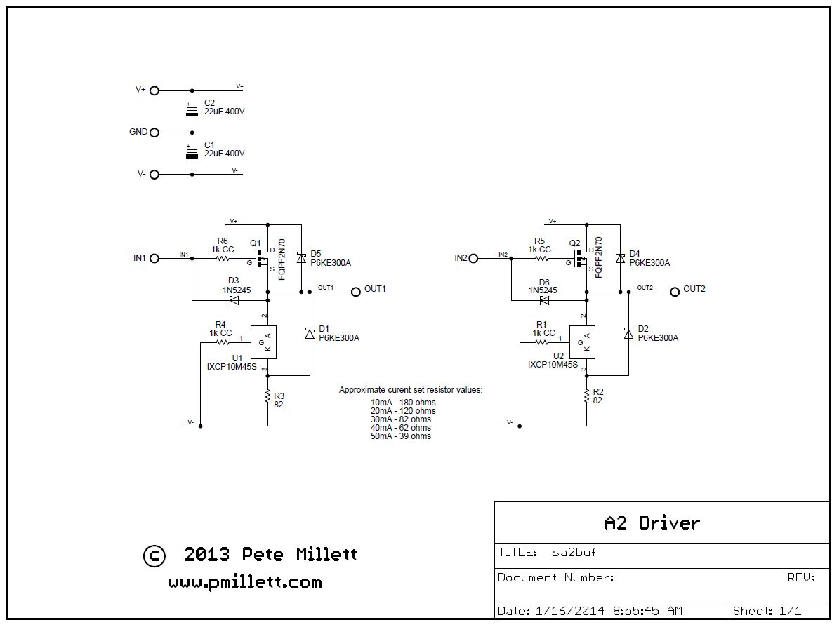
MOSFET A2 buffer
Here's a circuit that can be used to provide current drive to the grid of a power tube to operate in class-A2 operation (or download it as a PDF file):
This is a simple N-channel MOSFET source follower, with a CCS load using an Ixys IXCP10M45S part.
The bias (standing) current through the buffer is set by R2/R3 above. It seems to be not too critical... I wound up using 100 ohms, which gives around 25mA through each of the circuits.
Zener diodes D3 and D6 protect the gates of the MOSFETs from transients that could pop the gate oxide of the FETs. The TVS devices D1/D2/D4/D5 provide protection for the FET and CCS part during transients, shorts, and power-up/power-down conditions. They technically are optional, but I would recommend they be used.
This circuit floats between a positive (V+) and negative (V-) supply. Technically, it has no ground connection (like an opamp). I did provide spots for filter caps on V+ and V-, so there is a GND pad on the board, but it only connects to the caps.
Power supply rails need to be somewhere beyond the maximum positive and negative swings you need on the output. They can be considerably higher if you want, limited by the FET and IXCP10M45 breakdown voltages. I use +250V and -100V for the 815 amplifier. Do keep in mind that the power dissipation goes up with the voltage, since this is a constant-current buffer. Also, dissipation will go up when delivering large currents to the output.
Note that there is no bias network on the input to the buffer. You need to provide some DC bias, just like you would to the grid of a tube, and AC-couple the signal into the input with a coupling cap. The output will track ~4V lower than the input. A simple resistor to ground will give you about -4V on the output, which works well for quite a few "zero bias" transmitting tubes.
Here is an example of how it's hooked up (showing driving the grids of an 815):
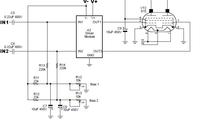
Another application for this would be to drive the screen grid of a power pentode (or beam tube). In this case you could DC-couple the input to the plate of a driver tube. The output will sit just below the voltage on the plate of the driver, which is just right for screen drive.
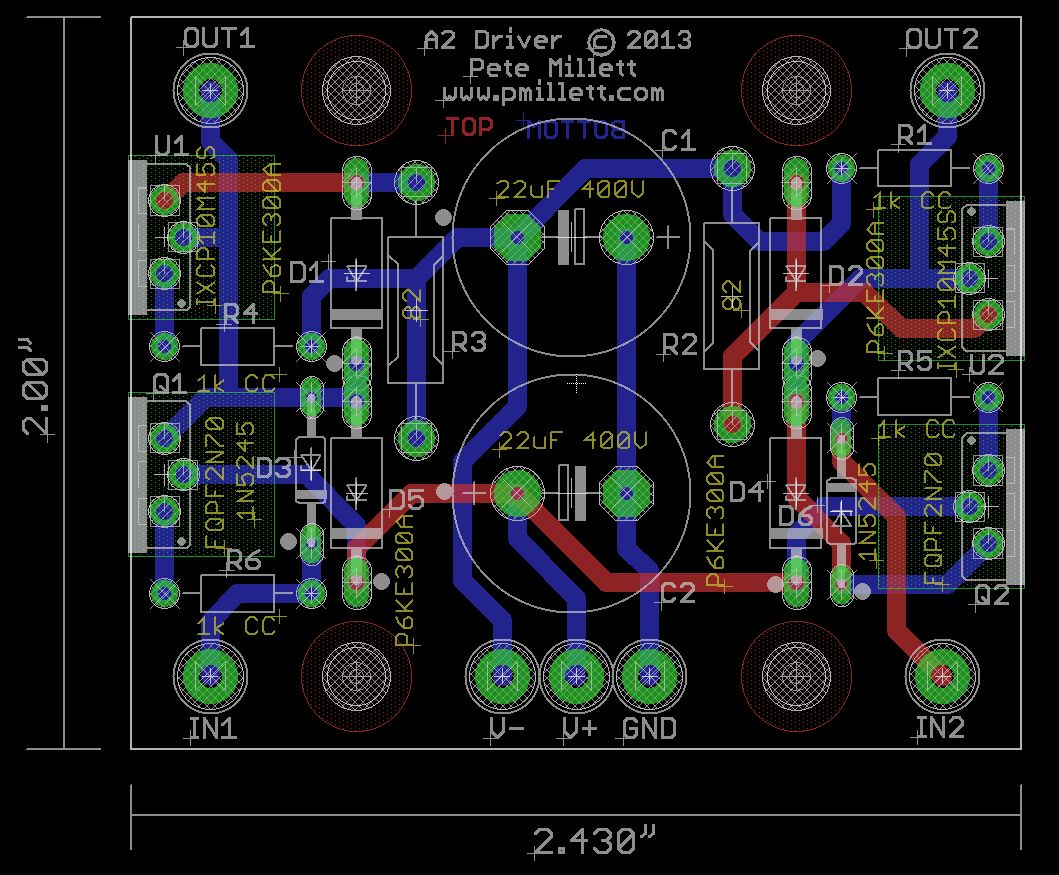
Here is the PCB, available on eBay:
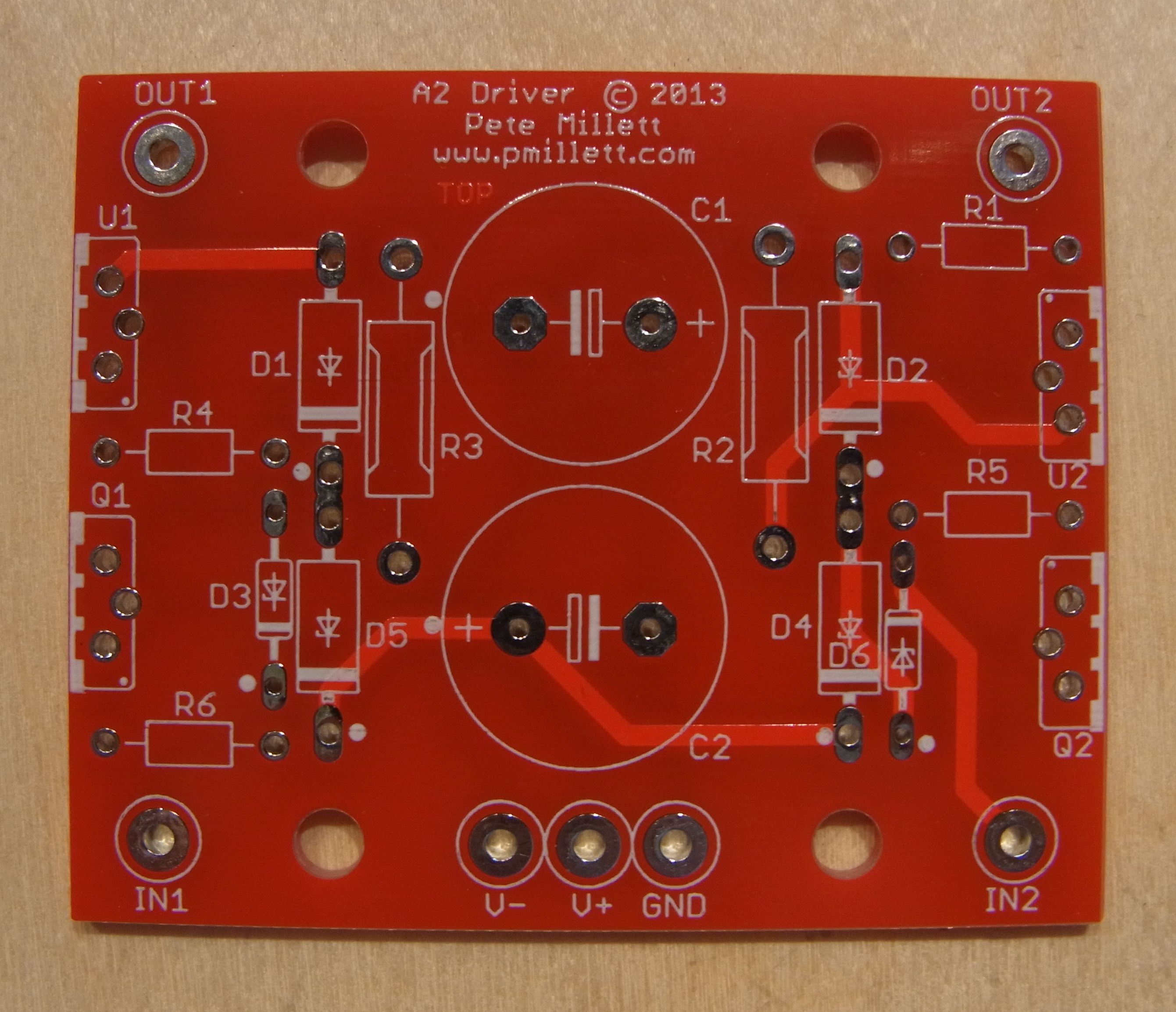
The assembled PCB:
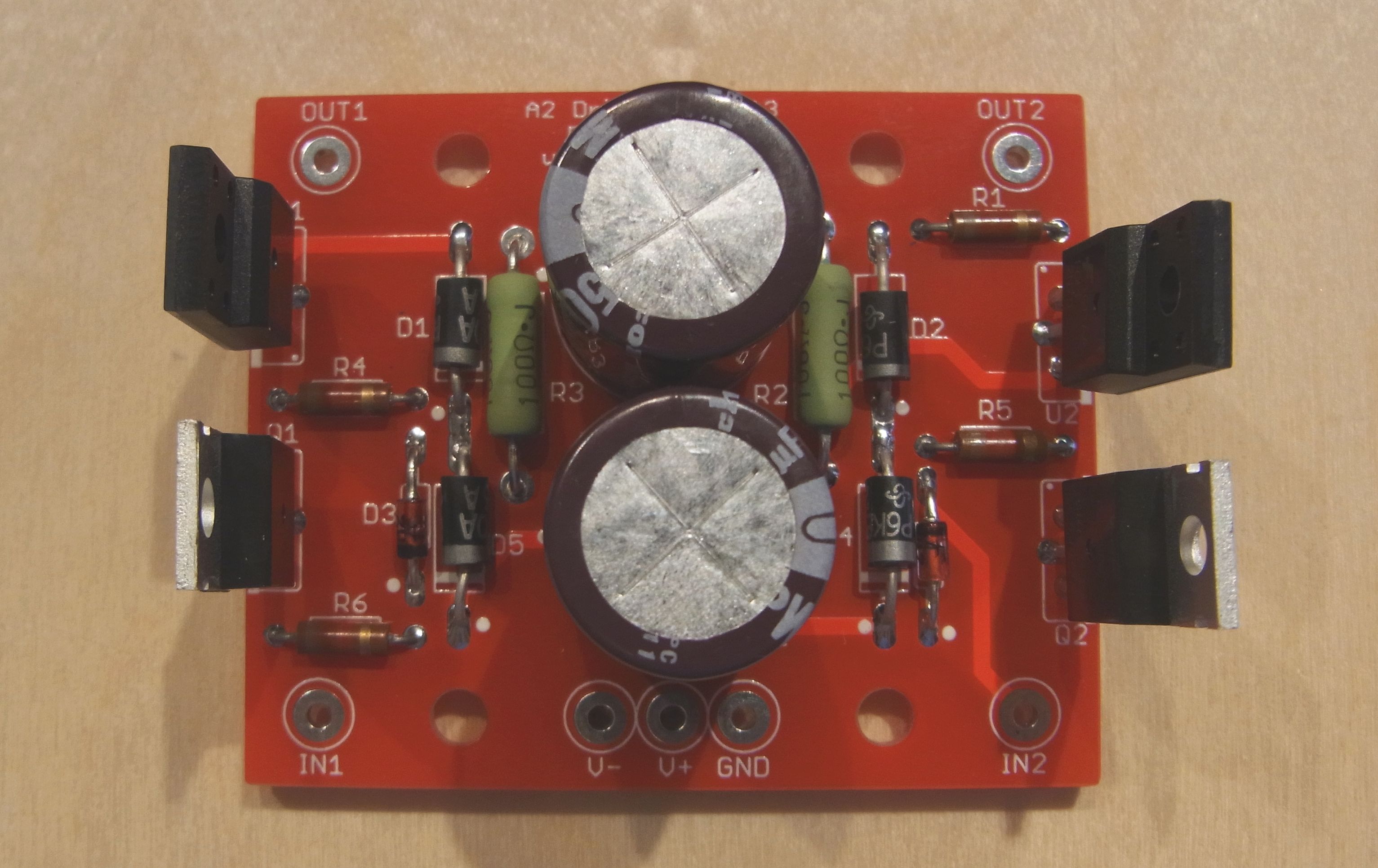
One little note - on Zener diode D6, the silkscreen label isn't visible because it's underneath D4. Also, the cathode dot on the silkscreen is at the wrong end - follow the component outline to locate the cathode end).
...and the PCB assembled onto the heatsink:
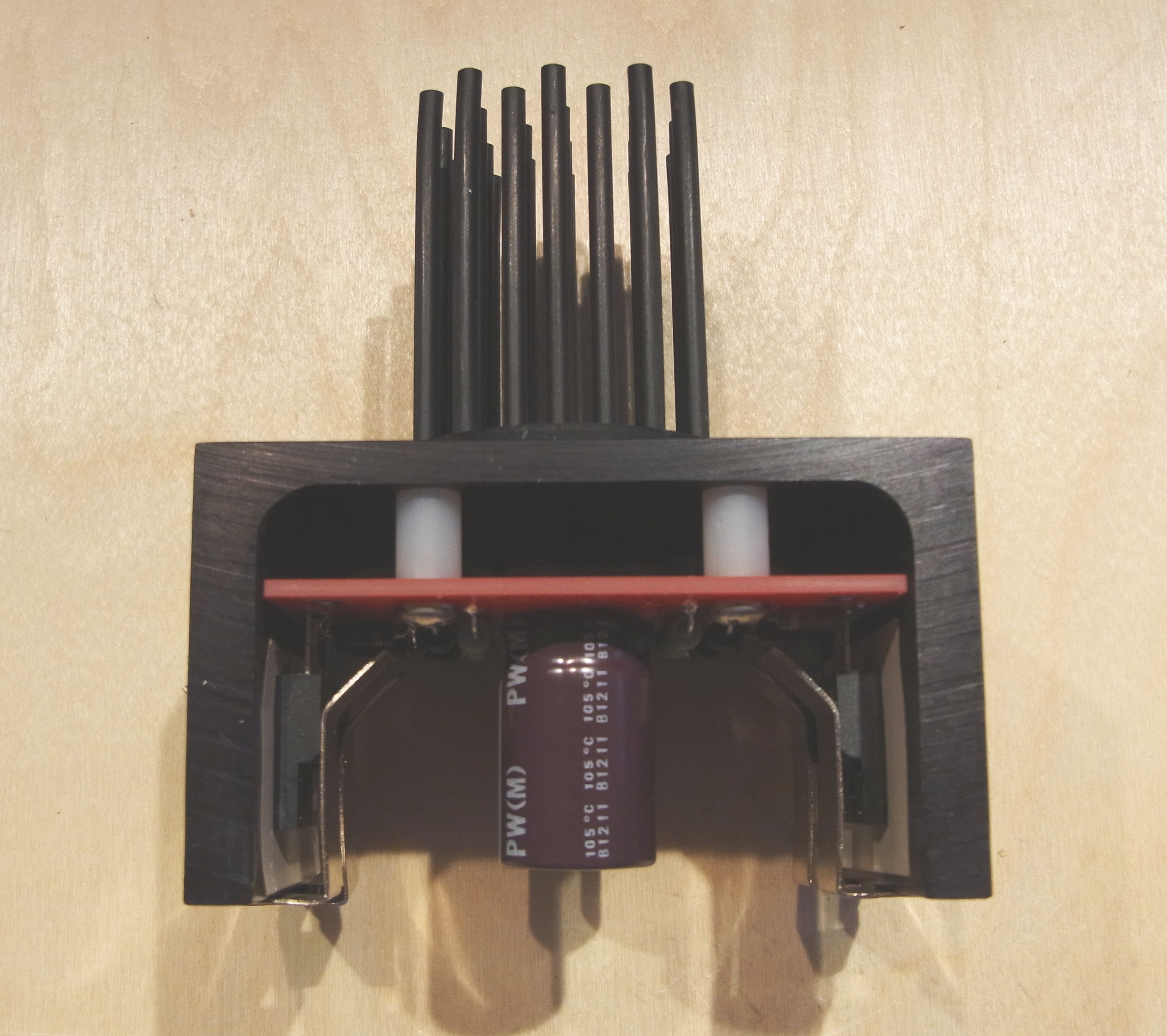
The heatsink is a very cool device (literally?) that I developed along with Landfall Systems. It allows you to get the heat generated up and out of the chassis. You just have to drill or punch one big round hole for the heatsink pegs to stick out of the chassis, and two small holes to mount it using screws.
Contact Landfall about the heatsink. You can also get a prototype bard from them that lets you build your own circuit using this heatsink.
Note that you need to space the power devices such that the bottom of the plastic body is about 1/4' above the PCB, so that the heatsink and clips correctly mate with the heatsink.
You can of course use some other heatsink method if you prefer.
You can download the BOM in PDF or XLS format. All the parts can be gotten from Mouser.