I designed and built a simple DC regulated power supply to drive the 300B filaments in the "Unnecessarily Complex 300B Amp" some time ago. Since then I have had a number of requests to buy PCBs for this circuit. I finally have gotten around to optimizing the design and now have some boards available. You can find the PCBs on eBay by clicking here.
Although I designed this mostly to use as a DC supply for tube filaments or heaters, it is a general-purpose DC supply that has many applications. Basically just add a transformer to get a regulated DC voltage in the 1.25V to ~25V range, at up to 5 amps. You can connect two modules to get a bipolar supply (for opamps, for example) - see below.
Here is the schematic (click on the image for a full PDF schematic):
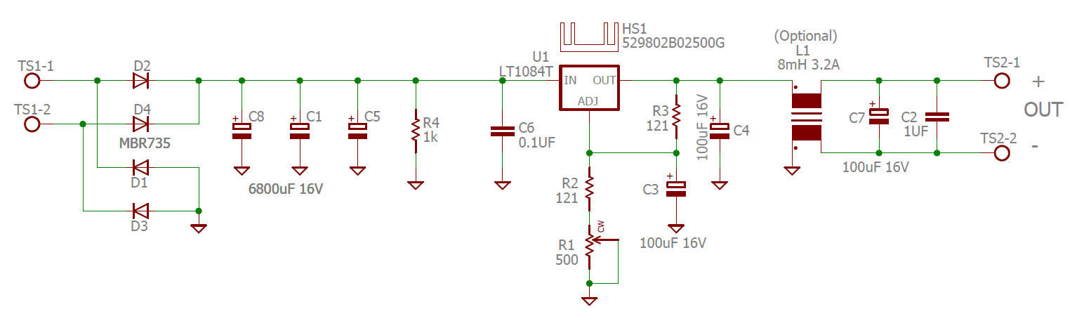
Just a simple rectifier/filter, LT1084 or LT1085 (or similar) voltage regulator IC, and a common-mode choke like the ones used on switching power supplies. The common-mode choke is optional - you can install two jumpers if you don't want it. It is intended to help reject common-mode noise that might capacitively couple across the power transformer from primary to secondary. It can also help filter rectifier recovery noise. Note that due to resistance in the common mode choke you need to adjust the voltage under load... you lose a couple tenths of a volt across the CML.
Note that if you are using this at a higher voltage like 10 or 12V, you will need to make R1, R2 and R4 higher resistance or they will dissipate more than 1/4 watt.
I designed the PCB to be the same form factor as the Tent Labs filament supply, which is a more complex voltage-controlled current source (which works very well, by the way). That way I could switch between the two without any major modifications.
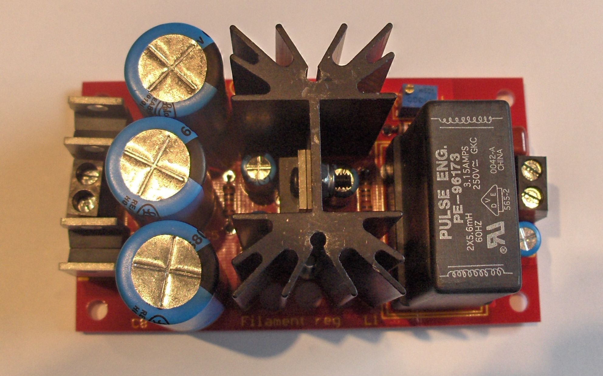
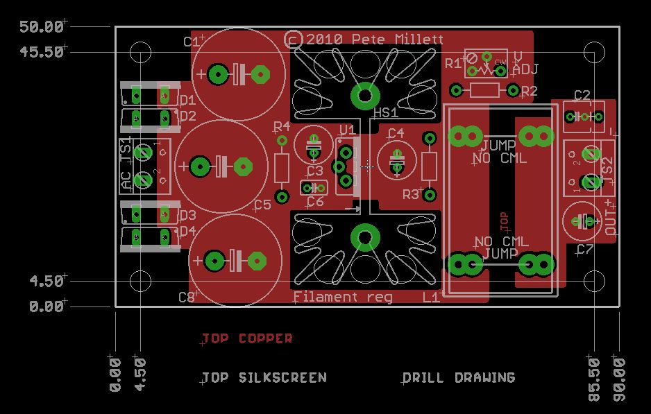
Here's what the PCB looks like (click for a full-size image):
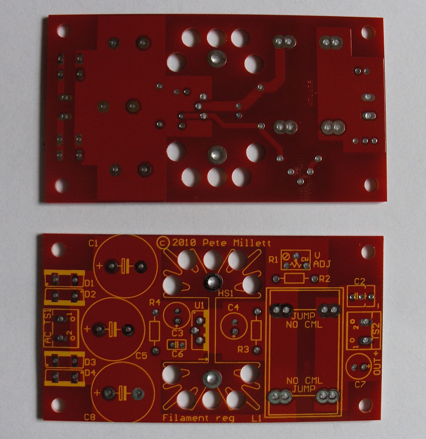
Dimensions (in mm):
You can download a BOM either in PDF or XLS format. I also have a Mouser project BOM that you can access via this link. Total cost for the parts is just over $20 each, plus the PCB. I'm selling them for $30 per pair on eBay.
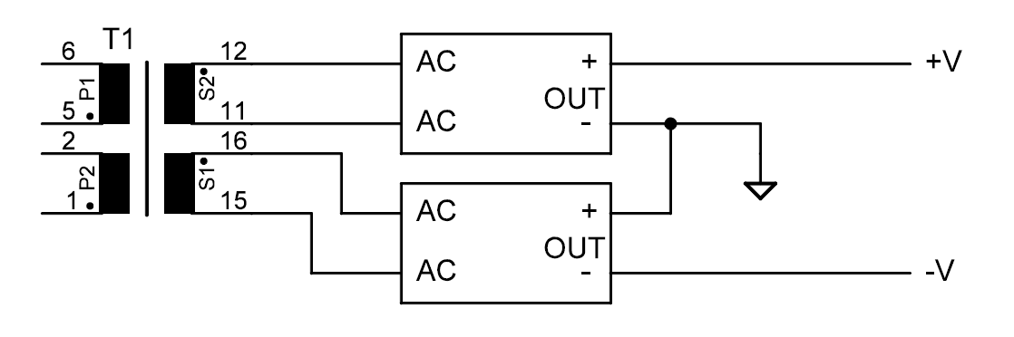
Output voltage and dual supply connection
The output voltage is set by the resistor divider (R1, R2, and R3) connected to the LT108x feedback pin, which is regulated at 1.25V below the output. For details, refer to the LT108x datasheet.
With the values shown in the schematic and BOM, the output can be adjusted from 2.5V up to 7.6V by adjusting the trimpot R1. If you wanted a range of 10V to 20V (for opamp supplies, for example), you could make R2 820 ohms and the trimpot R1 1k.
If you have a transformer with dual secondaries, you can use two of these supplies to make a bipolar (+/-) supply. You would connect two modules as shown below:
Input voltage and current
To maintain it's regulated output voltage, the DC voltage input to the regulator IC must remain slightly above the desired regulated output voltage (the minimum difference between input and output is referred to as "dropout voltage"). For the LT108x series, a 1.5V minimum difference is recommended. So, for a 5.0V regulated output, you should have 6.5V minimum at the input of the regulator (or output of the filter).
To determine what voltage the transformer secondary needs to be for proper operation, you need to consider this minimum voltage, the ripple voltage, and the voltage drop across the diodes. The peak DC voltage (top of the ripple waveform) is approximately [1.4 * (RMS transformer voltage)] - 1.0V, where the 1.0V is the drop across two diodes. The ripple voltage depends on the current output of the supply and the power supply capacitance (3 * 6800uF in the BOM, or 20.4mF). The ripple voltage is approximately I/(2*f*C), where f is 60 (60Hz mains) or 50 (50Hz mains). As an example, for a 1A load current and 60Hz mains, the ripple voltage would be about 0.4V.
If you add all this up: 6.5V (minimum input to regulator) + 1V (diode drop) + 0.4V (ripple) you get 7.9V. Now you multiply this by 0.707 to get the RMS voltage, which gives you 5.58V RMS. That is the minimum voltage you need for the transformer secondary. To keep the amount of power dissipated in the regulator as low as possible, you should use the next higher voltage available. In this case that would probably be a 6V transformer.
The RMS current rating of the transformer should be a minimum of 1.8x the DC output current. This is a general rule of thumb, and it does depend on the transformer itself. So for the 5V 1A output example above, ideally you'd want a 6.3V 1.8A transformer. Higher current ratings are good (2A would be a good choice here - the higher the current rating the cooler the transformer will run).
Now, if you're lazy like me, it is easier to use Duncanamps PSUD power supply simulator to get an idea about what you need. I entered the parameters for a 6.3V 2A transformer with 15% voltage regulation (typical for a cheap transformer). Here's the result:
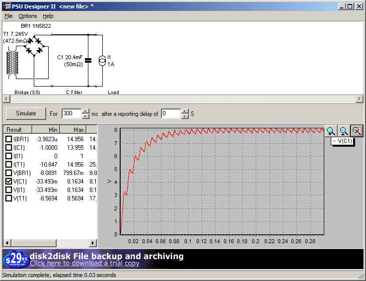
The minimum DC voltage (bottom of the ripple) is about 7.75V, which gives you 2.75V of dropout voltage for the regulator.
If you are using this for a filament supply, some guidelines: For a 300B at 5V and 2A, use a 6V (or 6.3V) transformer rated at 4A or more (a 5V transformer may work but is pushing the dropout voltage). A 2A3 is good with 5V at 4A. For 6V 1A (like for a preamp), you can use a 6.3V 2A transformer (or winding on a plate transformer).
Power dissipation
Nothing is free. If you have 1A of current flowing and 2.75V drop across the regulator, you are dissipating (I*R) or 1*2.75 = 2.75 watts of power in the regulator. That's why it is mounted on a heatsink - it gets warm.
So, the current you can draw from this regulator is limited not only by the regulator IC itself (the 1084 is good for 5A; the 1085 3A), but also by the power dissipated. The heatsink on the BOM is good for 5-7 watts, depending on how hot you're willing to let it get. You can get taller or shorter heatsinks that will fit the PCB if you need more or less power dissipation. And if you're clever you can figure out how to mount it to your chassis for additional heatsinking.
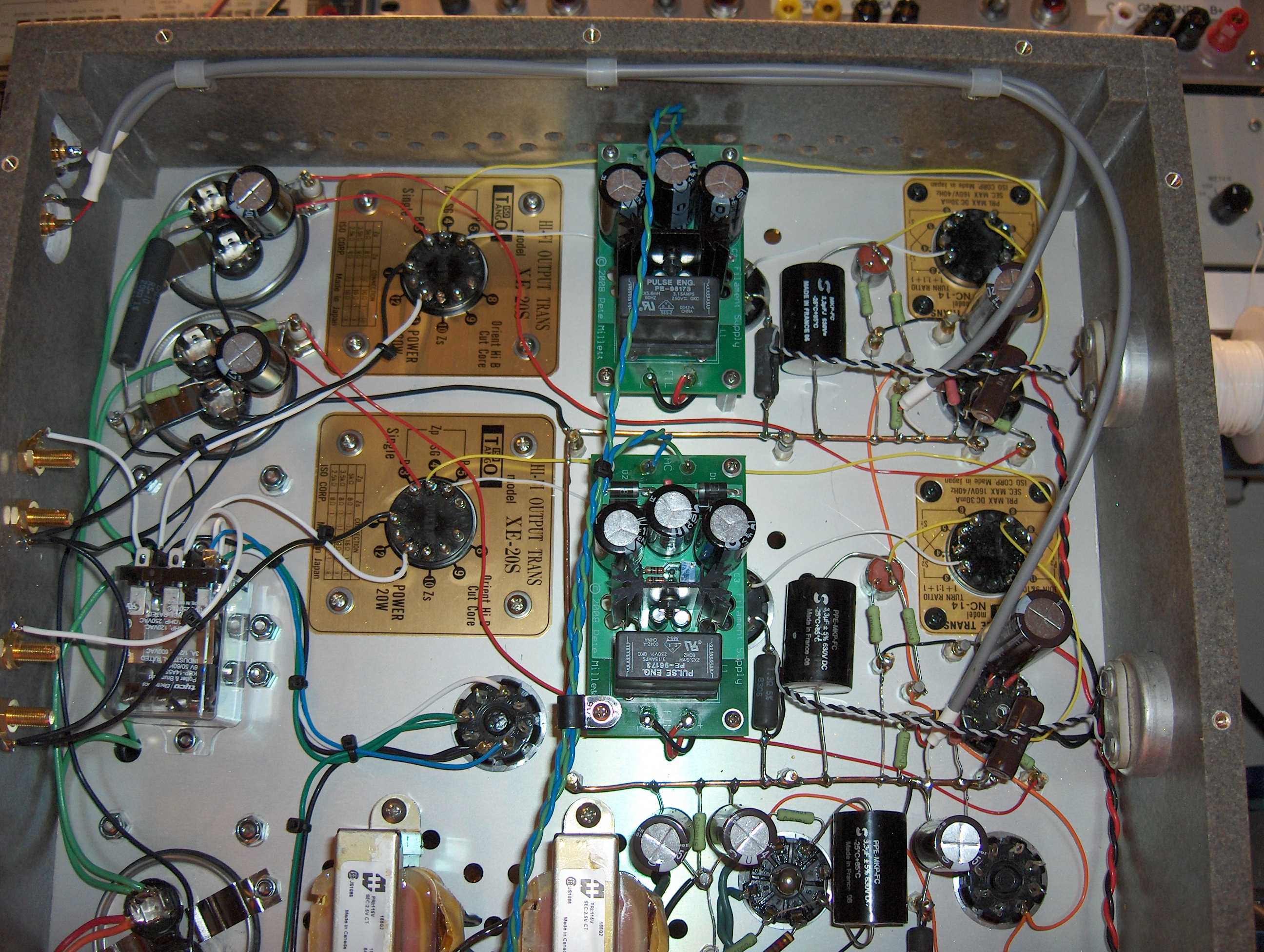
You can see a pair of the earlier version filament converters in this picture of the underside of the "Unnecessarily Complex 300B Amp". They are the two green PCB's...