ECC99 SRPP Headphone Amp
This little guy is a headphone amplifier that I designed mainly to drive the fine AKG K1000 headphones. K1000's are hard to drive, as headphones go. Their impedance is pretty typical of headphones, at 120 ohms... but they require a lot of voltage (power) to get to a good listening level. They're rated at 1 watt maximum, which corresponds to 11V RMS, and at their stated efficiency of 74dB/mW, you need 400mW of drive to get to 100dB, which is a good target for a maximum listening level. This amp will drive 325mW, which gives about 99dB... plenty loud for me.
My OTL tube amps can get close to this power level, but the problem is that the K1000's don't sound very good unless they're driven with a really low output impedance. They were designed to be driven by a "normal" power amplifier, with a Zo of only a few ohms. When you drive them with an amp that has, say, 30-50 ohms Zo, they sound very thin (especially in the bass).
So, I designed an amp to drive them.
This amp is unlike my other headphone amps in that it is NOT an OTL design. It uses an SRPP output stage, driving a special parallel-feed headphone output transformer made by Sowter in the UK. I bought transformers directly from Sowter in the UK, paid with a credit card, and got my transformers within 10-14 days in the US.
I used the current-production JJ Electronic ECC99 dual triode tube, which is an excellent audio tube. You can buy the ECC99 from Triode Electronics for around $14.00 each.
The transformer has three secondary windings which you can connect to get different output impedances. I put in a switch to let me select the middle (two windings in series) and highest (three in series) combinations. The Zo of the SRPP stage is so low that at the middle setting, the amplifier Zo is something like 7 ohms, which is great for the K1000's. On the higher setting there's more than enough voltage to drive even 600 ohm headphones.
An SRPP amplifier uses two tubes wired in series - the lower tube's grid is driven, and it works like a normal grounded-cathode amplifier. The upper tube does two things; it acts like a constant-current source, which provides a constant plate current to the lower tube, hence a very high AC impedance, and a near-horizontal load line. When the load is taken from the cathode of the upper tube, it also acts as a cathode follower, providing a very low source impedance.
Here's the schematic (SRPP amp, for K-1000 and other headphones) (47k PDF file)
If you are using this amp to drive something other than the K-1000's (which require a very low drive impedance), you might want to consider an alternate connection of the output - a current-sourced grounded-cathode amplifier. Taking the output from the plate of the lower tube is more like a "pure" triode amplifier, since in this mode the upper triode acts only as a current source, and not as a cathode follower. The output load - as reflected through the transformer - provides a load to the plate of the lower tube (in parallel with the upper tube), so the load line is dominated by the output load. With this connection, the output impedance is set by the Rp of the lower tube. You could even put in a switch to select between the two if you'd like.
Alternate schematic (current-sourced grounded-cathode amp, for "normal" headphones) (38k PDF file)
Link to transformer data sheet (Sowter 8665)
Link to JJ electronic ECC99 tube datasheet
Some Specs
These measurements were made on the prototype, with no output resistance in series with the output, and the output taken from the cathode of the upper tube (SRPP connection):
Maximum output (5% THD) into 100 ohm load Switch set to Low Z 4.2V RMS (176mW)
Maximum output (5% THD) into 100 ohm load Switch set to High Z 5.7V RMS (325mW)
Maximum output (5% THD) into 300 ohm load Switch set to Low Z 4.4V RMS (65mW)
Maximum output (5% THD) into 300 ohm load Switch set to High Z 6.4V RMS (137mW)
THD at 1V RMS, 1kHz into 100 ohm load Switch set to Low Z 1.0%
THD at 1V RMS, 1kHz into 100 ohm load Switch set to High Z 0.8%
THD at 1V RMS, 1kHz into 300 ohm load Switch set to Low Z 0.9%
THD at 1V RMS, 1kHz into 300 ohm load Switch set to High Z 0.7%
THD residual is virtually all second harmonic, giving the characteristic "single ended triode" signature
Freq response 20-20kHz -1.0dB/-0.3dB ref 1kHz 1V RMS, either output Z selected... -3dB down at 70kHz
Noise referenced to 1kHz 1V RMS -65dB (probably near my measurement limit)
More Pictures (by popular demand?)
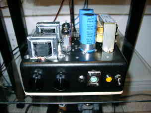
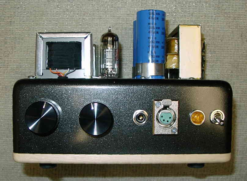
Front view
The knob on the left is the volume control, and the one on the right is the impedance selector switch. A standard 1/4" headphone jack is next to the XLR connector, which connects directly to the K-1000's without using the extension cable.
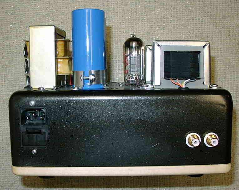
Rear View
Just a filtered, fused power inlet and the input RCA jacks (isolated from the chassis).
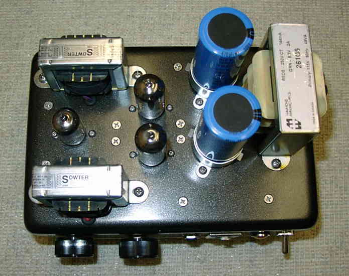
Top View
The 12AU7 is to the left, and the two ECC99's to the right.
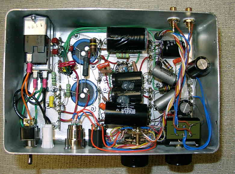
Inside Chassis
Pretty crowded inside here. The large black capacitors are the output caps (10uF), and between them are the cathode bypass caps for the output (also paralleled by some smaller orange drop caps). The metal-cased caps are "Vitamin-Q" paper in oil caps coupling between first and second stages. Cathode bypass caps for the input stage are at the far right. All the transformer output wires run to the rotary switch, which selects the impedance. The green wires running around are the AC tube filament supply.
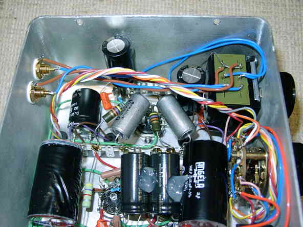
Inside chassis (power supply side)
Here you can see the AC wiring, as well as the power supply. The two terminal strips contain the filter (some call them snubber) parts on the transformer secondaries, as well as the rectifier diodes. Below that is the C-R-C filter for the B+. The 100K 2W resistor is a bleeder. You can just see the cathode resistors for the output stages, paralleled with the orange drop caps (and the electrolytics at the very bottom edge).
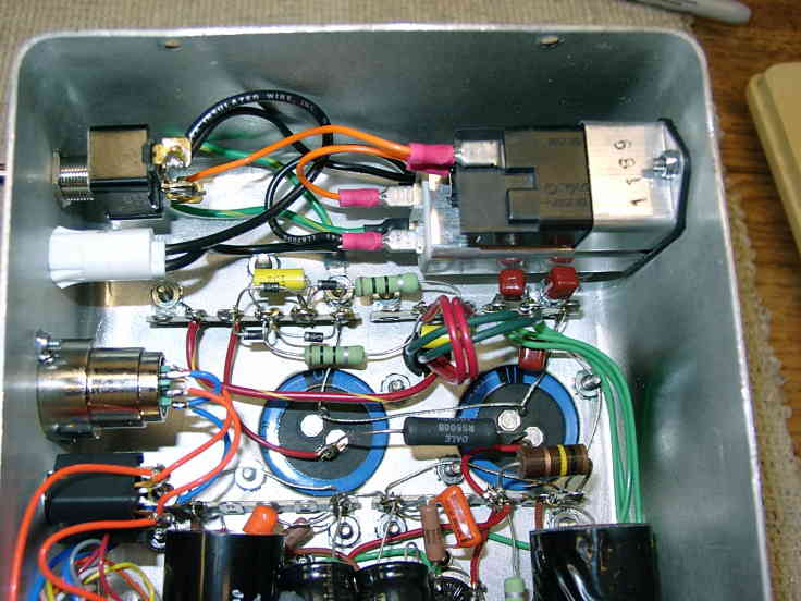
Inside chassis (input side)
Another view of the input side. The little can electrolytic at the top left is a B+ filter for the input stage, connected to B+ through the 4.7K 1W resistor you can see. An ALPS 29mm volume control is at the far right. The 47K 1W resistors are the plate loads for the first stage. You can see one of the plate resistors, and a little blue resistor that connects to the grid of the upper tube, for one of the output stages. The rest are hidden under the capacitors.
Some construction hints
As you can see from these pictures, the inside of this chassis (which is 6" x 9" x 3") is really crowded. I used this chassis (which is a deep-drawn aluminum box) because I had it - I would advise using a larger chassis, maybe 9" x 12", or even larger. If you use a bigger chassis you can separate the power supply (especially the transformer) from the other parts, and don't have to worry so much about laying out the parts so that everything fits. Especially if you are inexperienced in point-to-point wiring, it's a lot easier if you have room to spread things out and get the soldering iron in there without melting anything.
Even crammed together like this, the amp is VERY quiet. No audible hum or noise.