High-frequency filament supply
PLEASE READ - Commercial usage of information on this site:
I consider all the information that I post here to be in the public domain. So, you can use it however you want, for commercial or non-commercial use.
That said, I would appreciate it if you at least let me know if you are going to use any of the circuits or especially PCB Gerber files to make commercial products, or to sell bare PCB's.
There are some cases where products are being sold not only with my permission, but active involvement. The "Millett Hybrid" effort and others at HeadFi are examples (and excellent models of how the DIY community should work, in my opinion). There are other cases where I have asked vendors to sell PCB's as a service to hobbyists. And there are other cases where companies are manufacturing and selling PCB's, chassis, etc. without contacting me at all.
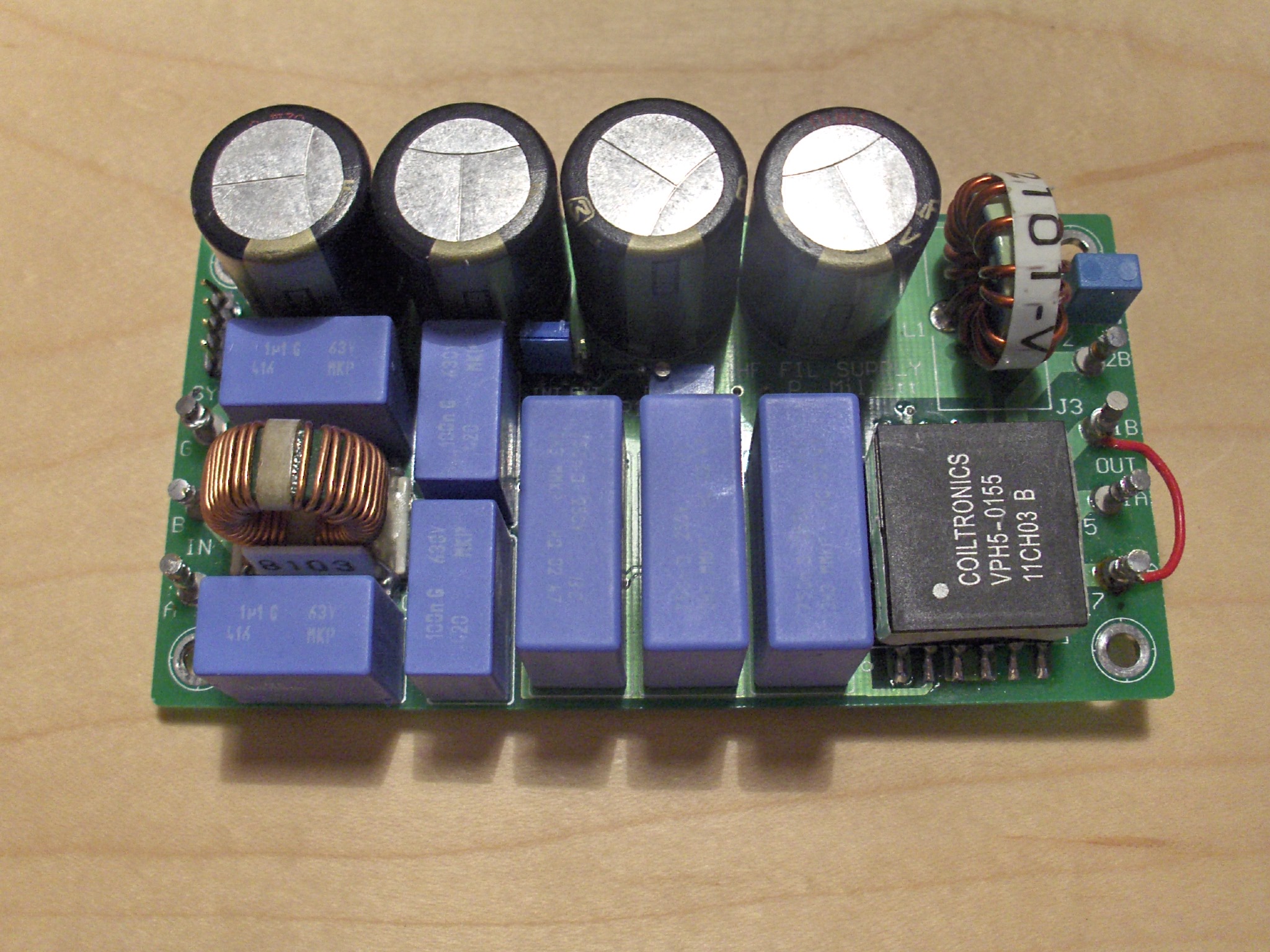
This is a high-frequency heater supply that I built for a shoot-out at the European Triode Festival. It takes low-voltage AC in, and puts out a more-or-less sinusoidal output at 100kHz. It's designed to drive a 300B filament, at 5V 2A, or other filaments of similar or lower power. The secondary windings can be configured in series for a 5V (300B) or 6.3V (6B4G) filament, or in parallel for a 2.5V (2A3) filament.
Here's the what the output looks like, set up for 5.0V, driving around 1A. Sorry for the crappy picture - I need to get a new PCI HPIB card to talk to the scope!
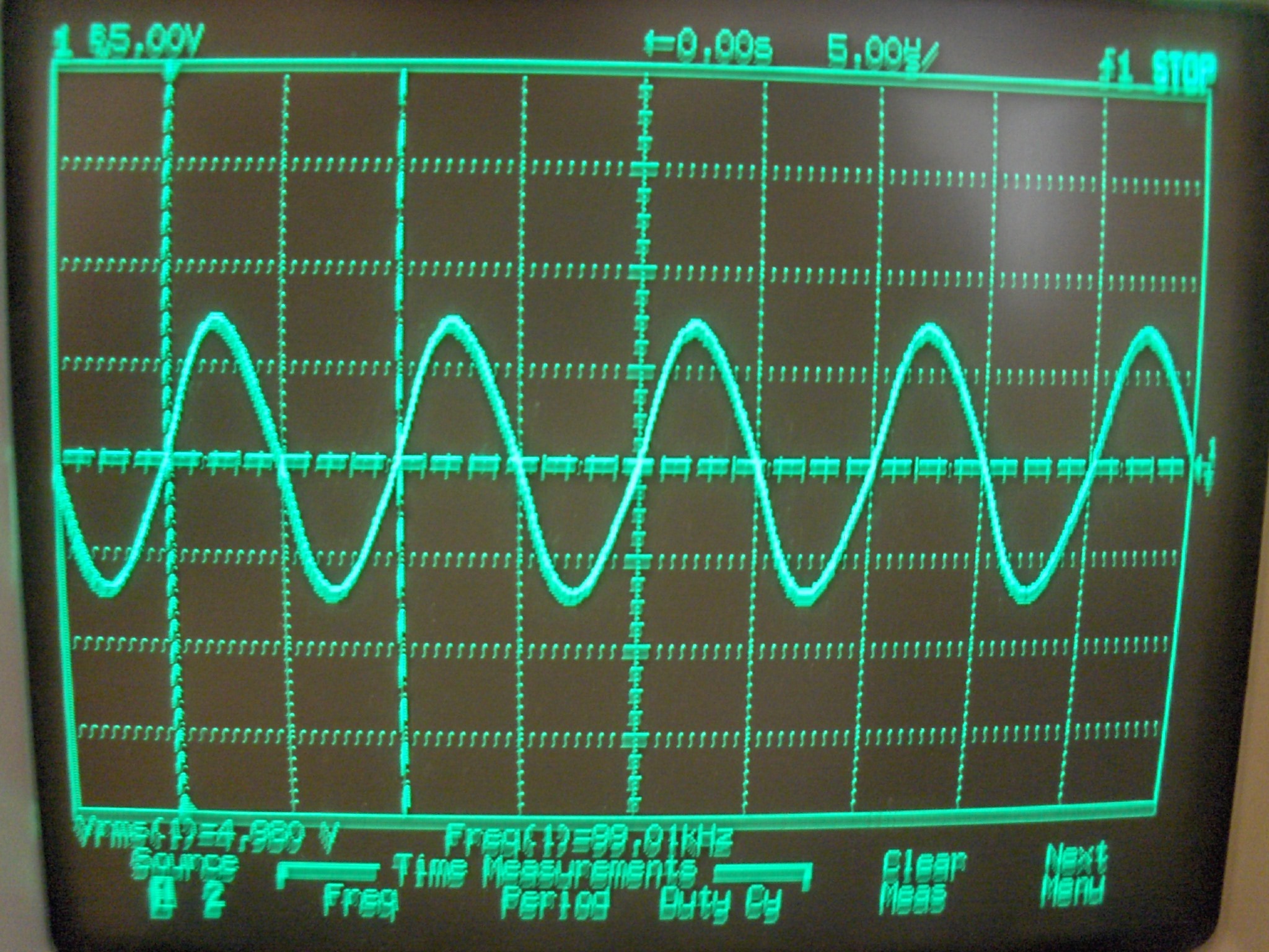
The theory behind this is that a 100kHz signal, even if it causes "hum" heating a DHT filament, is inaudible because it is such a high frequency.
It fared quite well in the shootout, pretty much ties with constant-current DC, and voted better than either regular AC or constant-voltage DC. Of course your results may vary...
I have not perfected this design. It works OK, though it just barely works with 10 watts output. It could be improved by using better MOSFET's, I think, and the recirculation diode (D1) in the buck stage gets quite warm, so a synchronous power stage might be a better bet there. But it does work pretty well for lower loads, less than 10 watts, as-is. It would probably also work better with a higher inductance transformer (and correspondingly smaller resonant capacitor), and a higher input voltage. That would keep the peak currents lower, which are quite high in this design.
At one point I thought it might be nice to commercialize it and sell PCB's, but I never did it. So, I thought I'd post it here for all to see, and maybe inspire somebody to further the work.
Here is the schematic (107kB PDF file). The circuit uses a UC3872 IC from Texas Instruments (Unitrode), which is designed to run a resonant lamp ballast for fluorescent tubes. It contains a buck regulator stage, and a push-pull resonant controller. The buck stage is used to regulate the amplitude of the output signal, which is fed back after being rectified and filtered to DC. The push-pull stage drives an output transformer, which is made resonant by adding a capacitance across the transformer primary.
Here's a text BOM for the PCB as well.
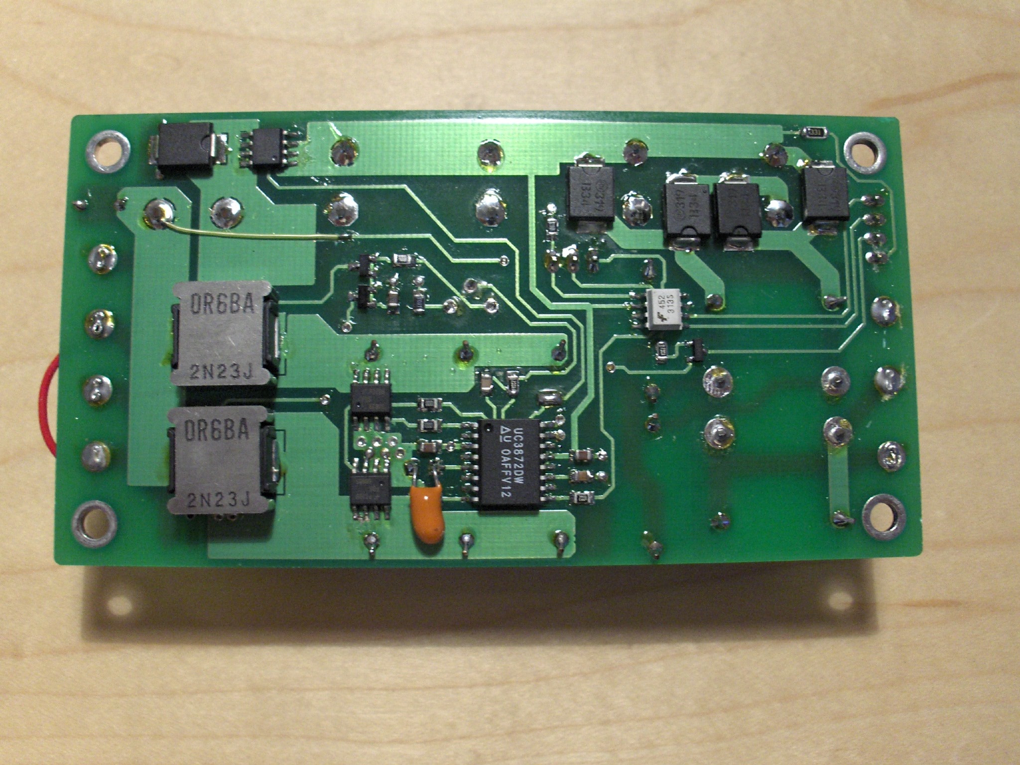
If you're interested in doing more with this, here is the Eagle CAD schematic, PCB BRD file, and the PCB Gerber files (46kB ZIP archive). Note that there is an error on the PCB - note the yellow wire visible in the photo of the PCB back side. Pin 9 of the UC3872 is supposed to connect to the downstream side of the buck inductor. Oops...
If you do take this design and modify and/or sell it, please let me know, as per the request above. Thanks!