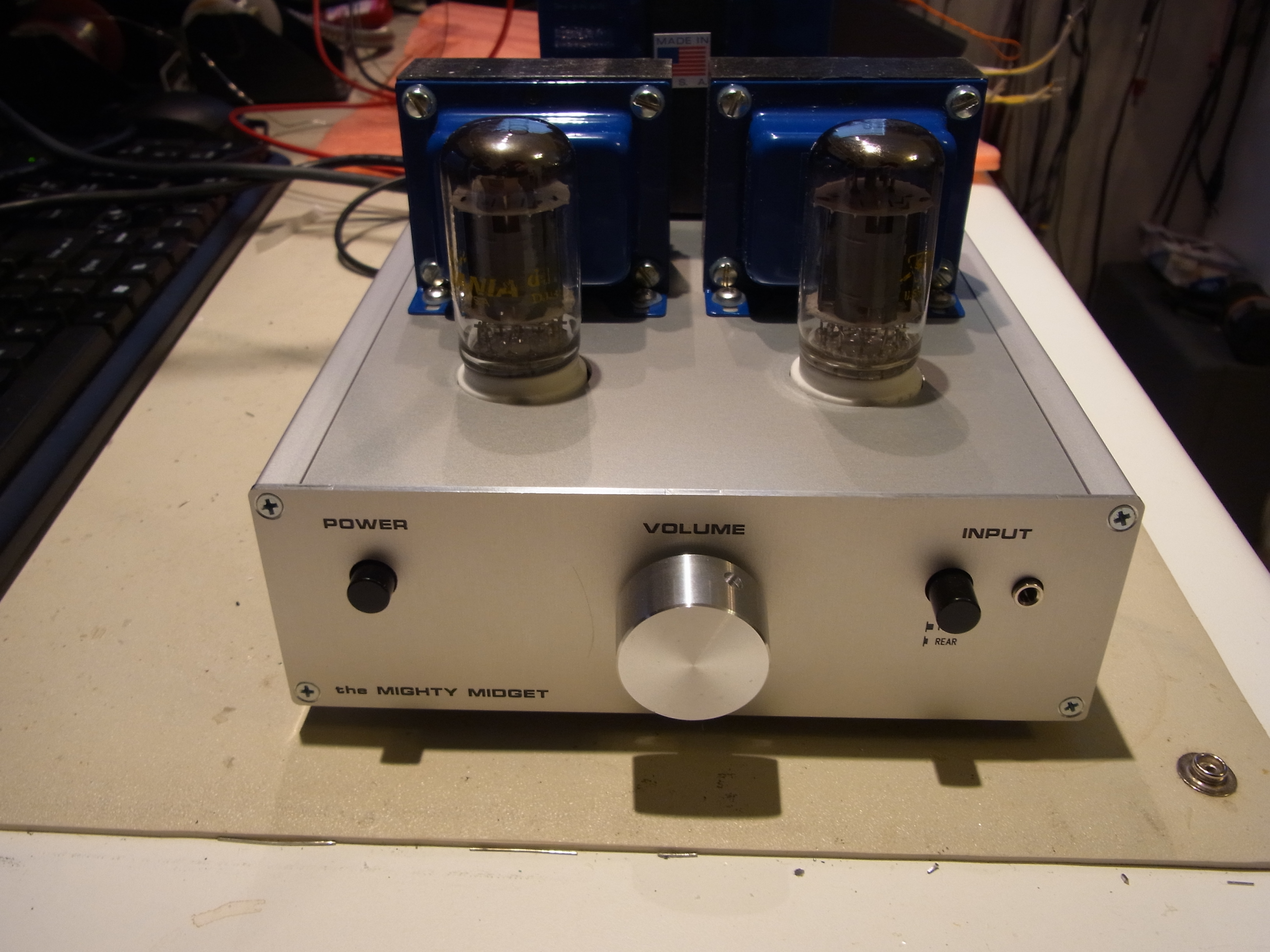
The "Mighty Midget" (originally in AudioXpress 05/08)
I am now selling PCB's for this project. See my eBay store (seller "pmillett").
UPDATED 8/25/2020 - Updated the BOM to reflect EOL components. Note that the speaker terminal is unavailable, so the BOM has a pair of binding posts to connect the speakers. You will need to connect these to the PCB with wires.
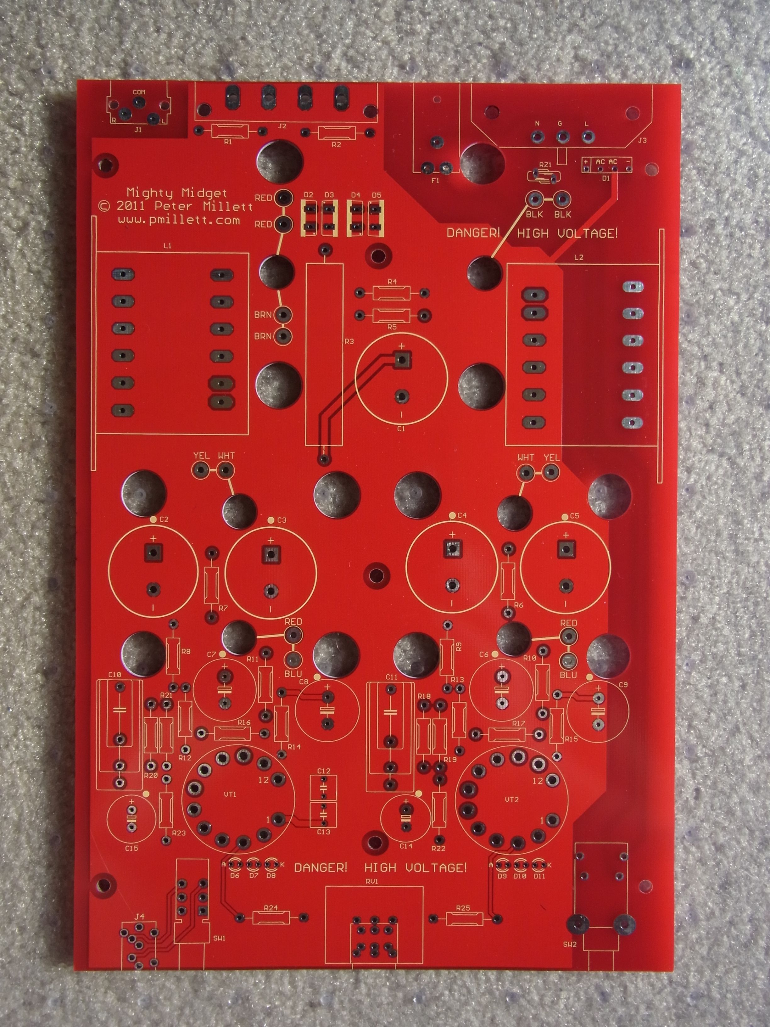
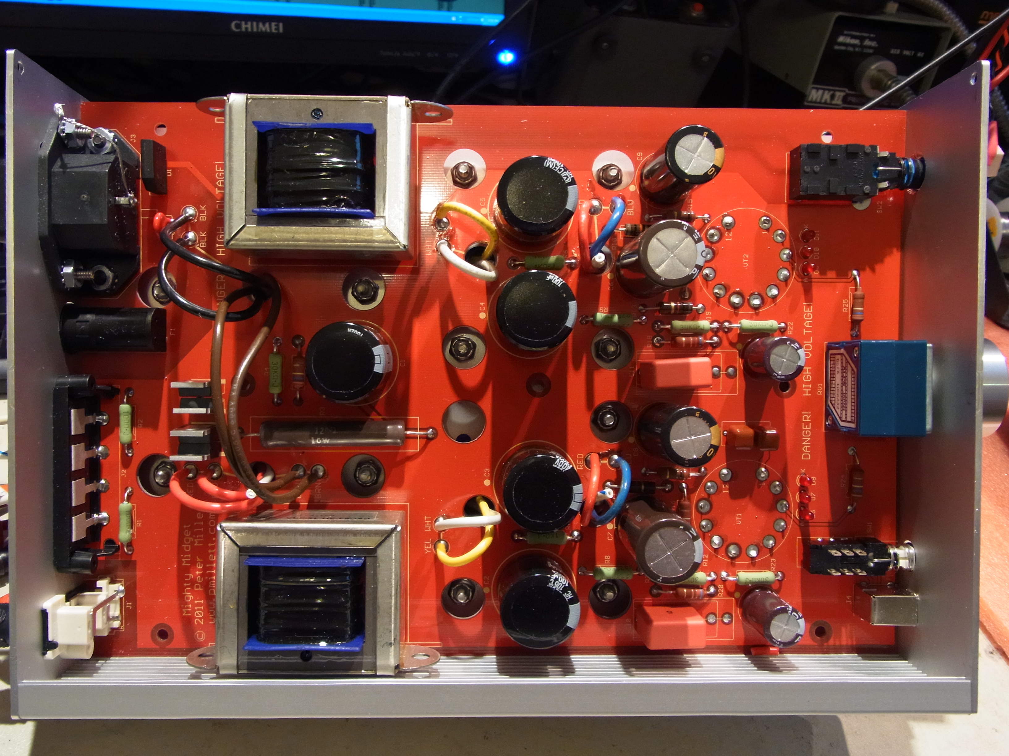
UPDATED 12/19/2011 - I've made some small tweaks to this design and put it on a PCB:
My goal in re-designing the Mighty Midget was to make it as easy to build as possible for a beginner to build. To that end, everything except the output transformers are mounted on the PCB, including the (frightening to a beginner) AC wiring. Though it doesn't guarantee success, it does raise the odds.
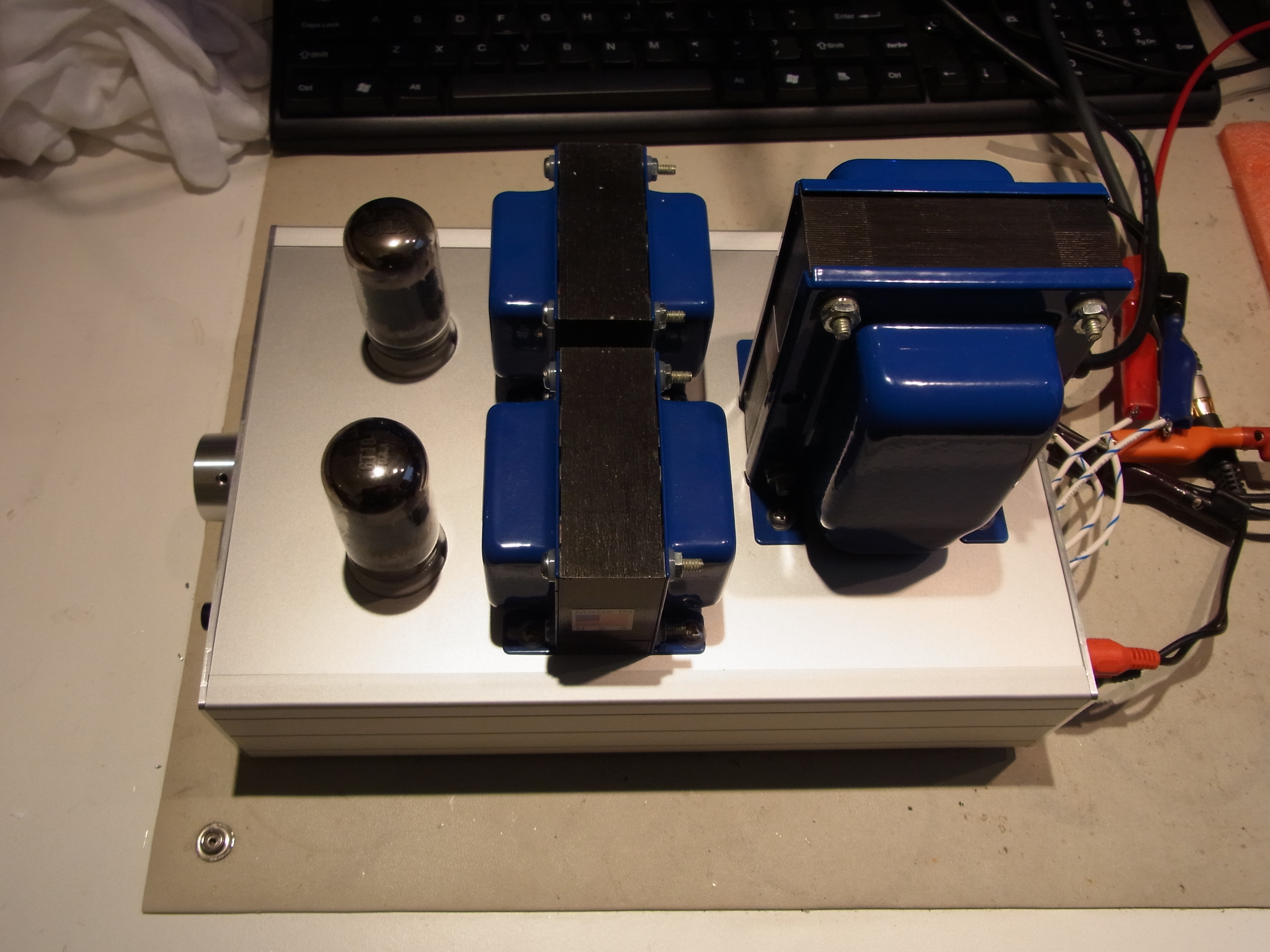
I used Front Panel Express to make the case for the PCB, using their side profile extrusions. This lets you poke parts (connectors and switches) out both the front and the rear of the box. I also had Edcor make a custom PCB-mount choke - Edcor is very good at fulfilling requests like that - so you can buy them as well as the transformers from them.
The schematic has changed a little bit. Mainly, I used a resistive divider to generate the screen voltage instead of a zener. This removes the power-down instability and squeal that forced me to add a power-up muting relay.
Here is the new PDF schematic, and BOM (PDF) or XLS. There is also a project you can access at Mouser: https://www.mouser.com/ProjectManager/ProjectDetail.aspx?AccessID=5055dac998
If you want to order the enclosure from Front Panel Express, you can just tell them you want to order their quote # 900825 - that will include the panels, side extrusions, and hardware. Or, you can download my FPE files and customize them (ZIP archive). (If you're observant you might notice that there is an error or two on my chassis - they are fixed in the files).
And some additional photos:
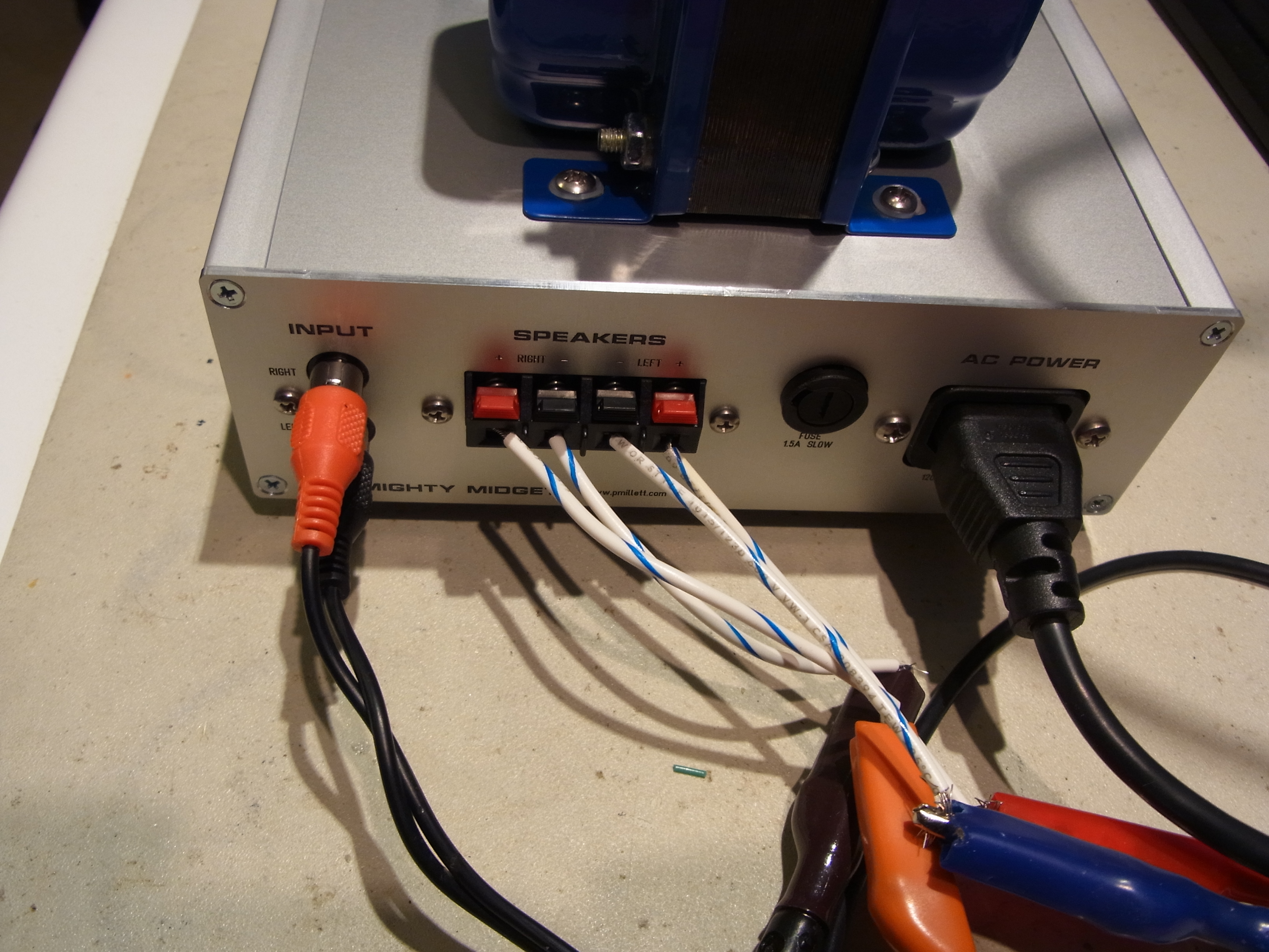
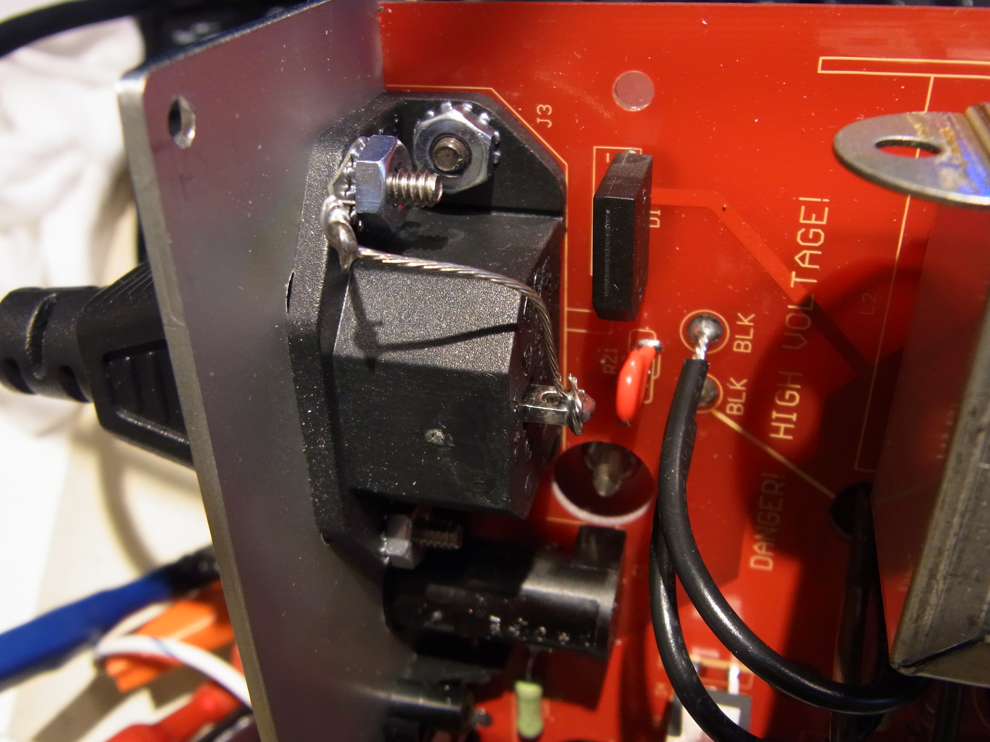
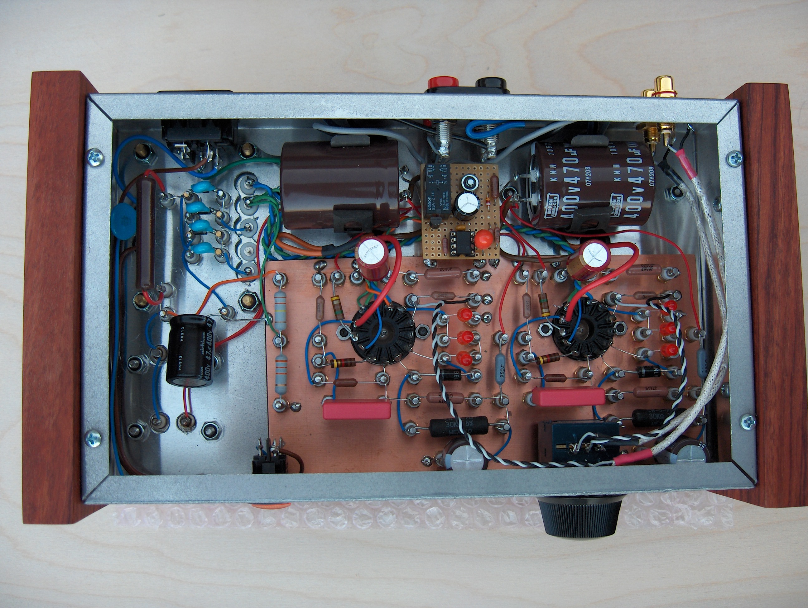
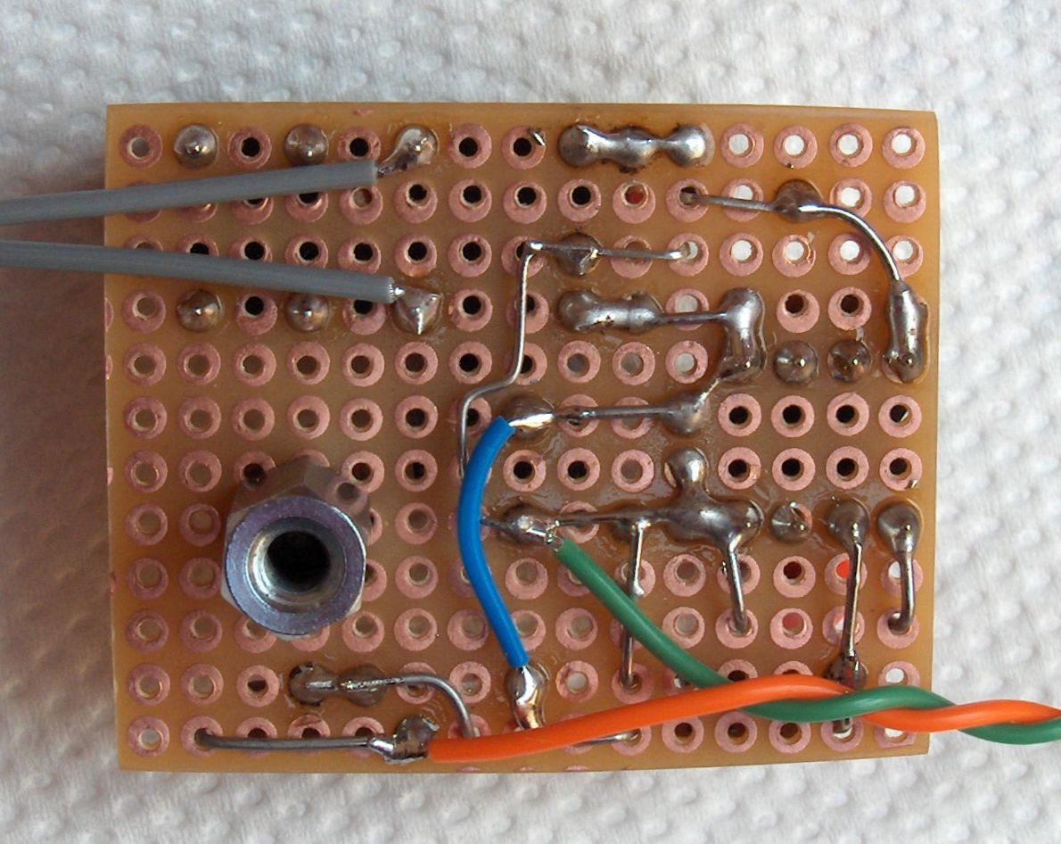
Note in the last photo the wire that connects the case to ground. Turns out that this is important - without it the amp was noisy and tended to oscillate. So do ground the chassis!
As per usual, I'll sell these PCBs on eBay.
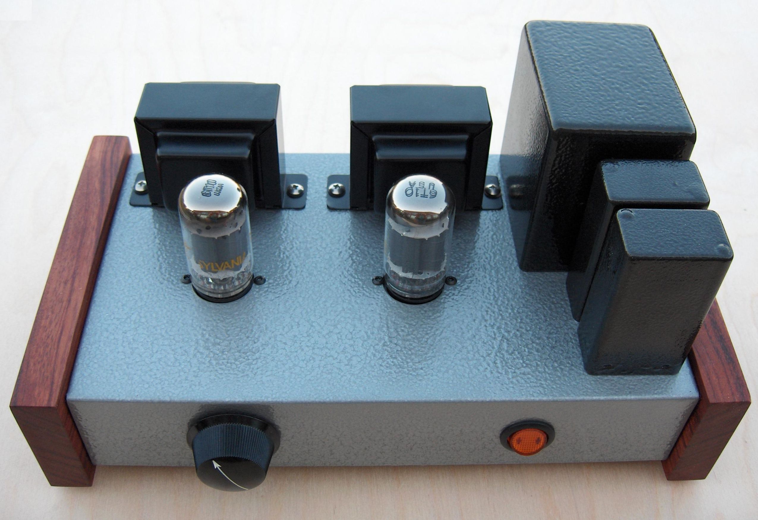
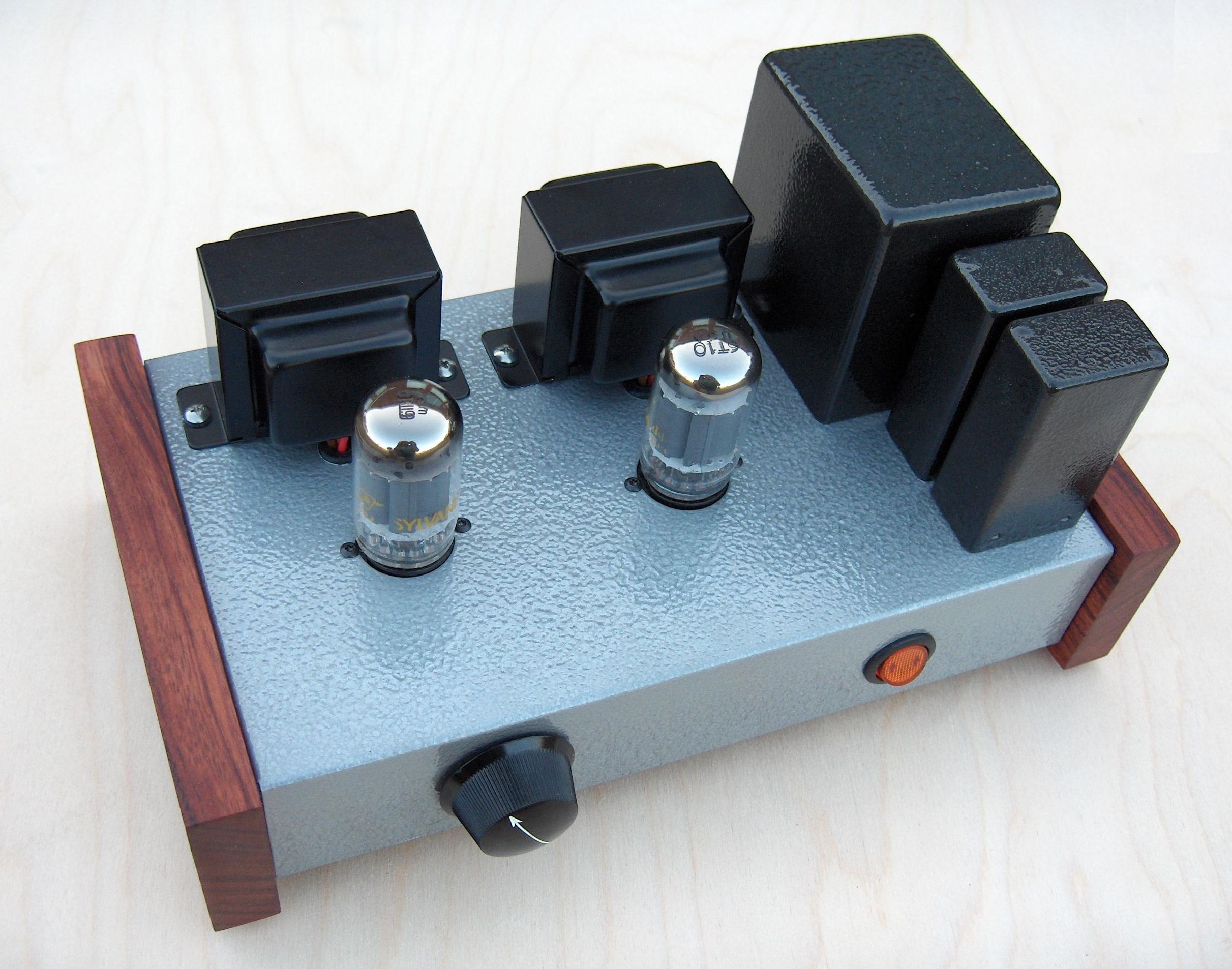
The "Mighty Midget" is a simple single-ended pentode amp that uses inexpensive compactron TV tubes. It puts out about 3 watts per channel, and uses only one (two-section) tube per channel.
This project was published in audioXpress, May, 2008.
In summary, the amp uses 6T10 tubes, which contain dual-control pentode and power beam tube sections. The dual-control pentode is used as a regular pentode amp (with a trick of biasing up G3 to get linear characteristics). The beam tube section is used in pentode mode, with about 10% plate-to-grid feedback to get decent distortion and damping factor. No global feedback is used.
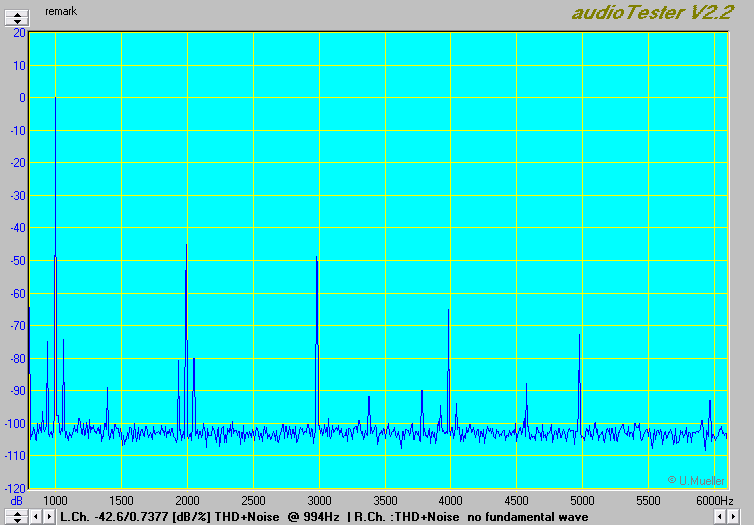
With a B+ voltage of about 300V, the amp puts out about 3.5W per channel, while dissipating under 10W on the plates of the output tubes. THD at 1W into 8 ohms is about 0.7%. You can see the FFT below...
The amp has a modest damping factor, with an output impedance of 3.5 ohms or so. It turns out that this sounds really good into my inexpensive Fostex FE164-based speakers, which tend to be a little brassy sounding on a low-output-Z amp.
I used small 7k SE OPT's that I found in Akihabara (Tokyo), but an Edcor XSE-10-8-8k should work well, as would a small Hammond SE OPT.
Anyway...
Since many of the photos and details are hard to read in the magazine, posted on this page are all the photos, schematic, and mechanical files for you to build this amp. Enjoy!
The schematic (144kB PDF file)
Mechanical layout:
PDF of the mechanics (128kB PDF file)
ZIP archive with AutoCAD DWG and R12 DXF files (144kB)
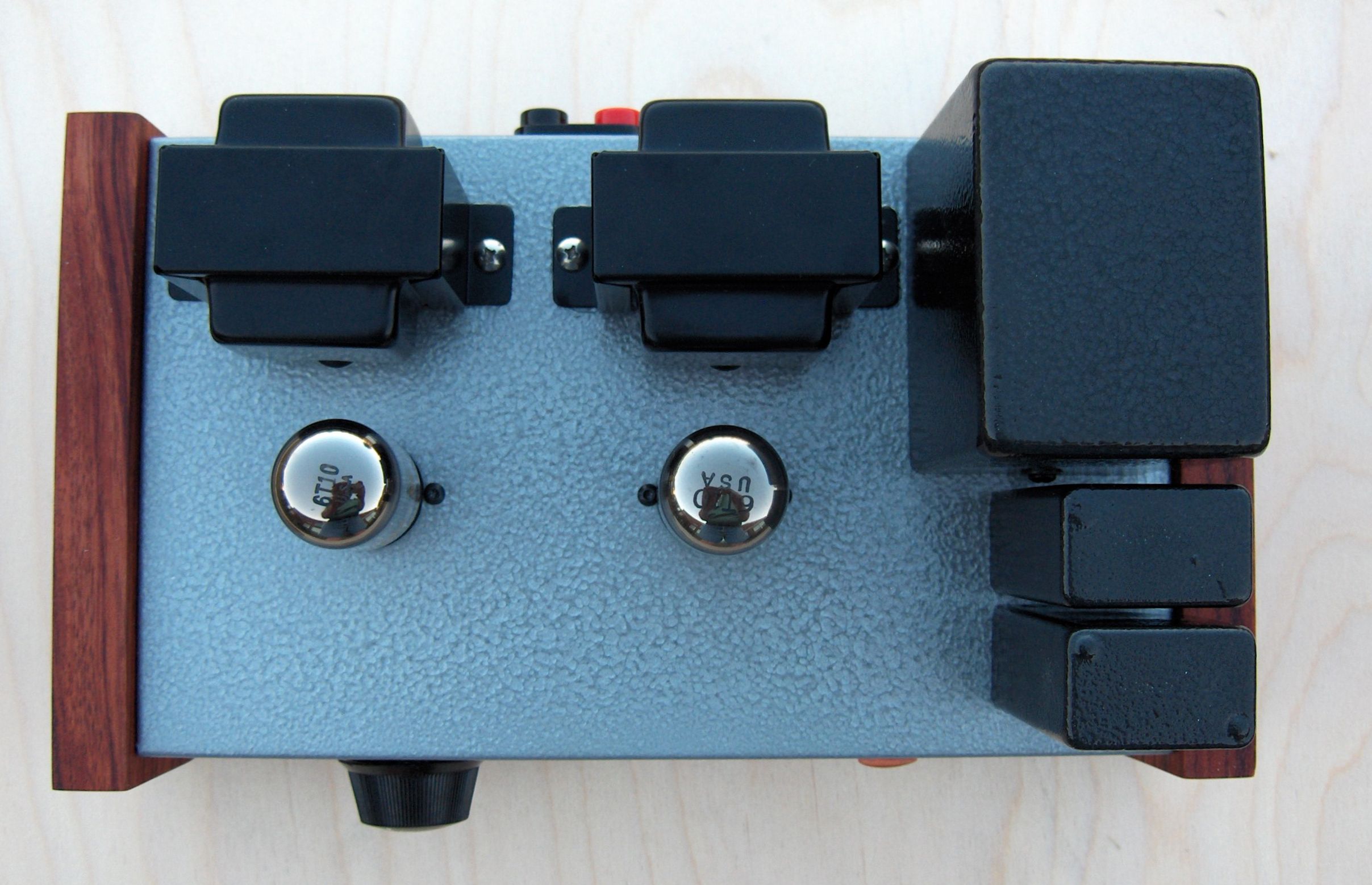
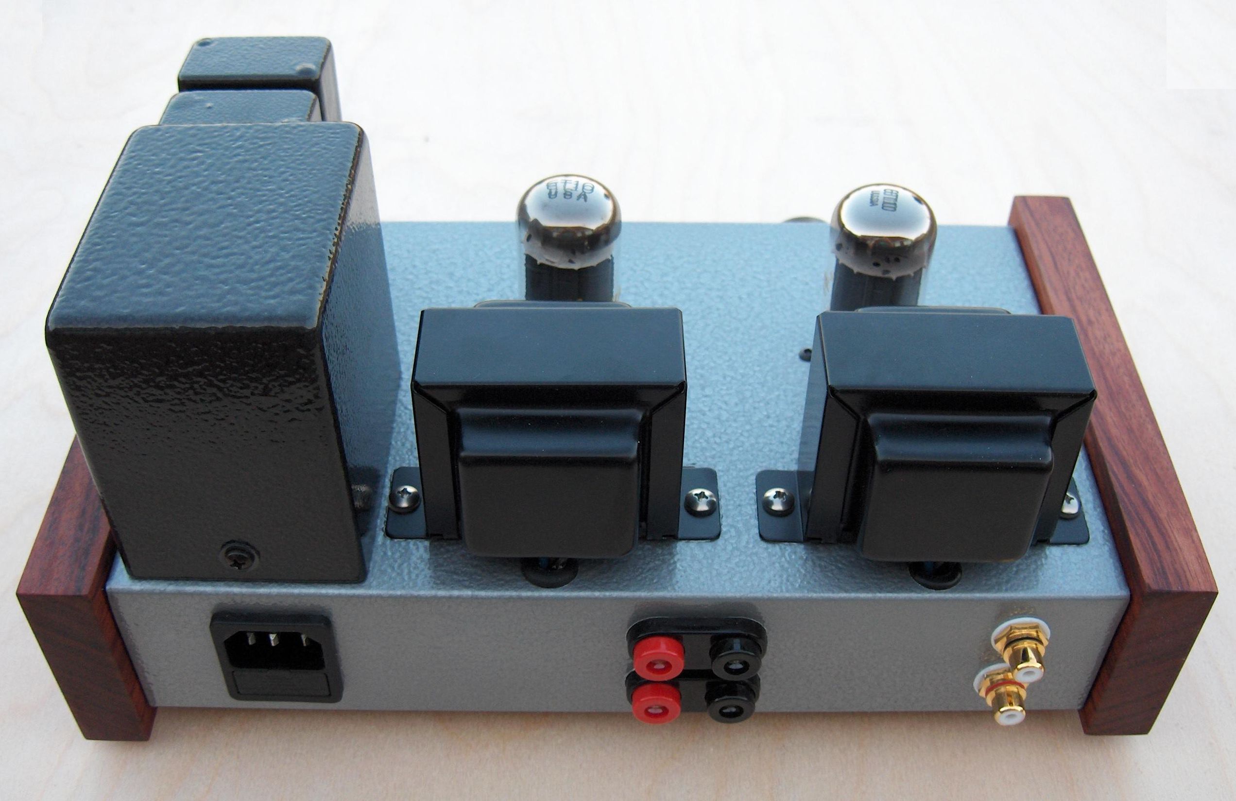
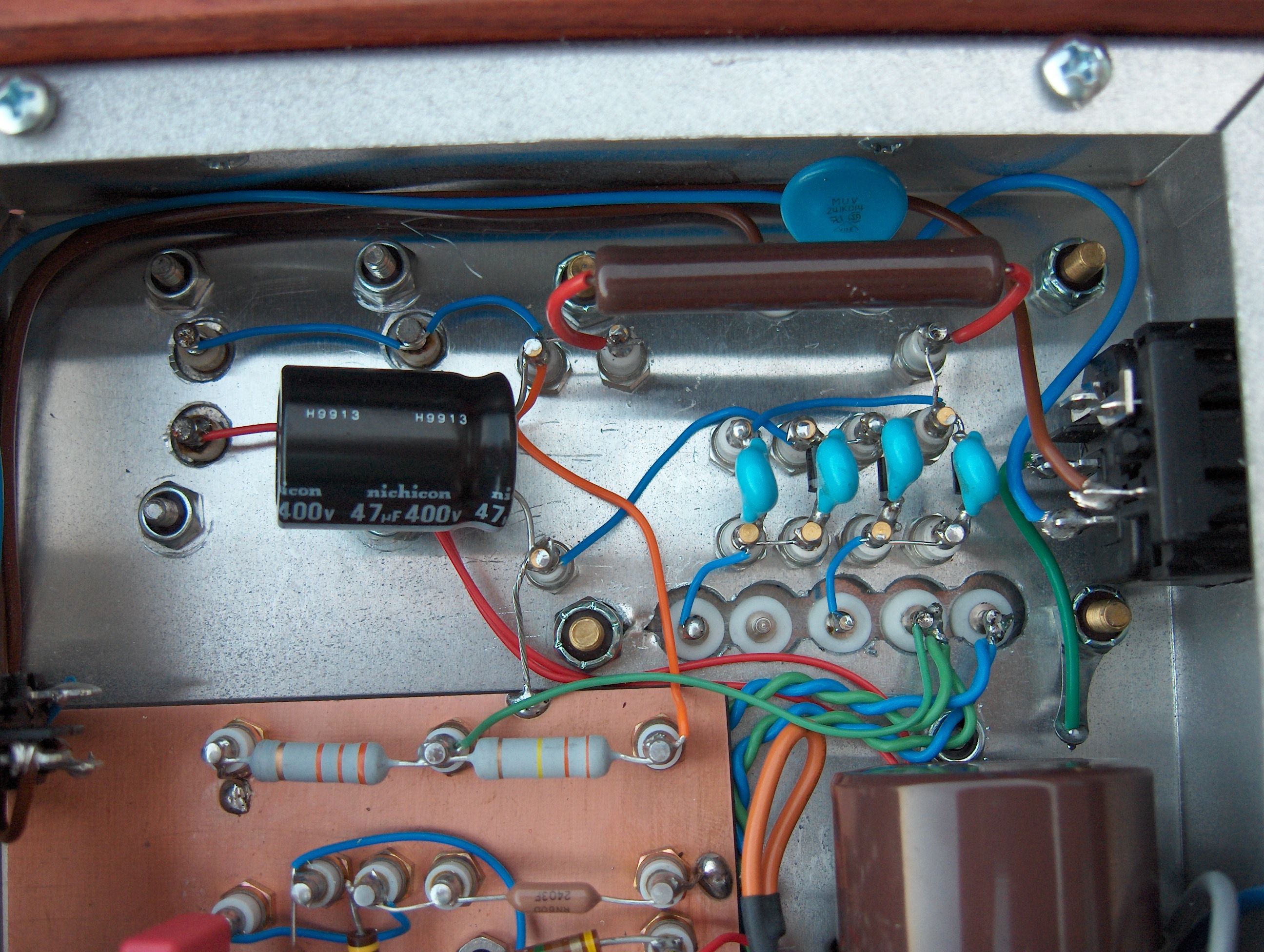
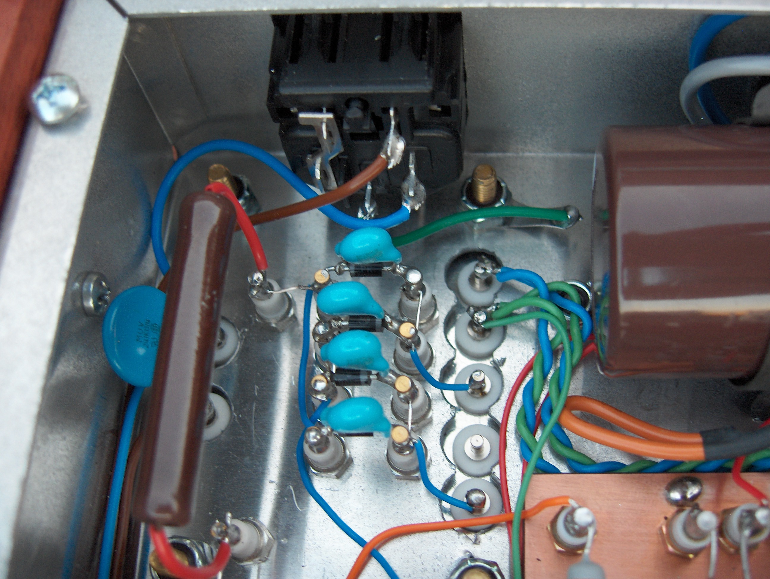
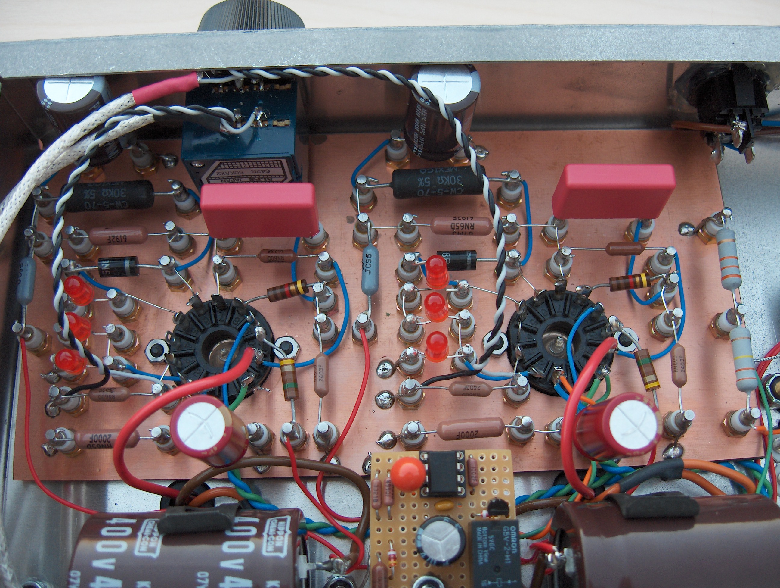
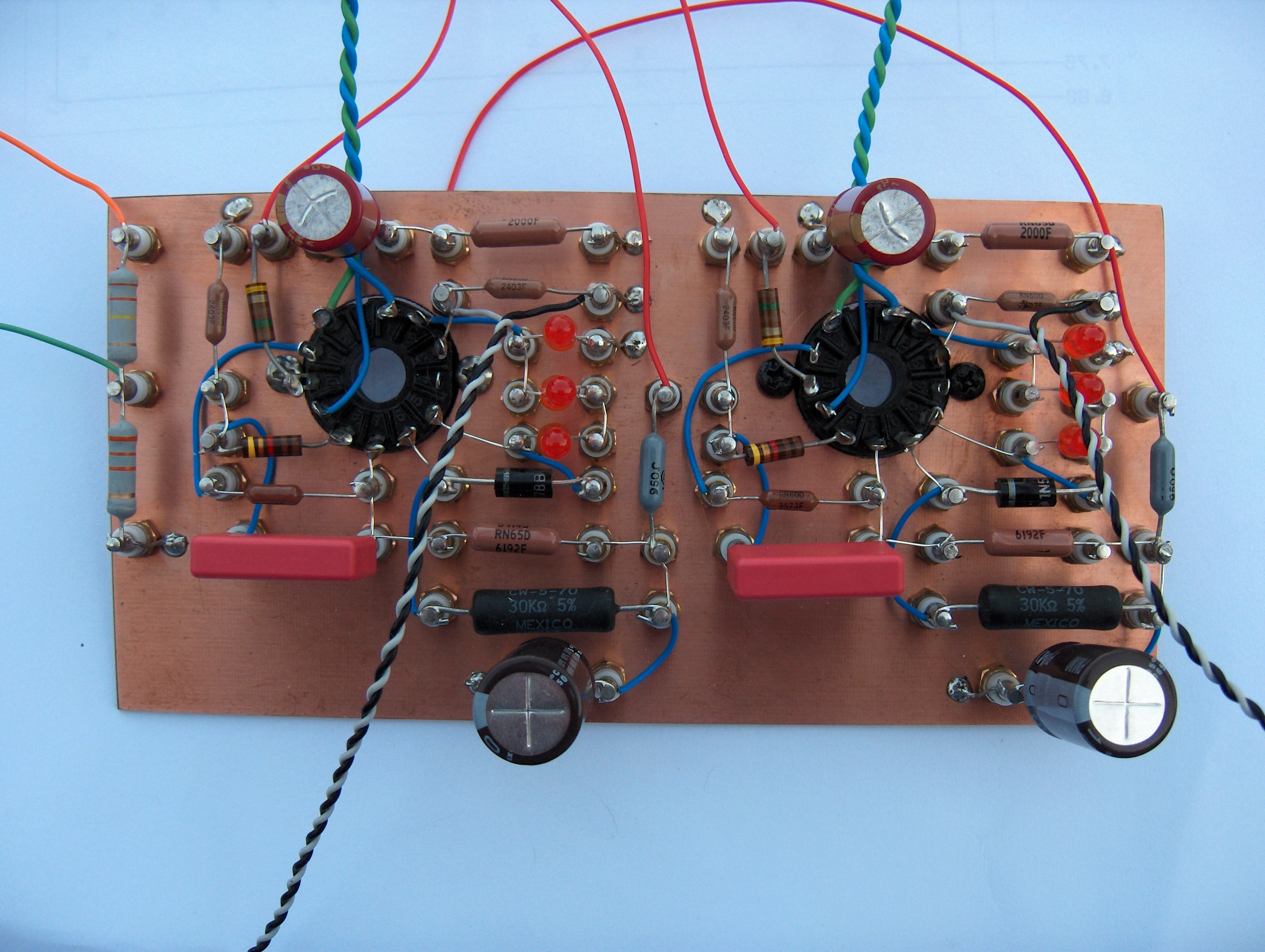
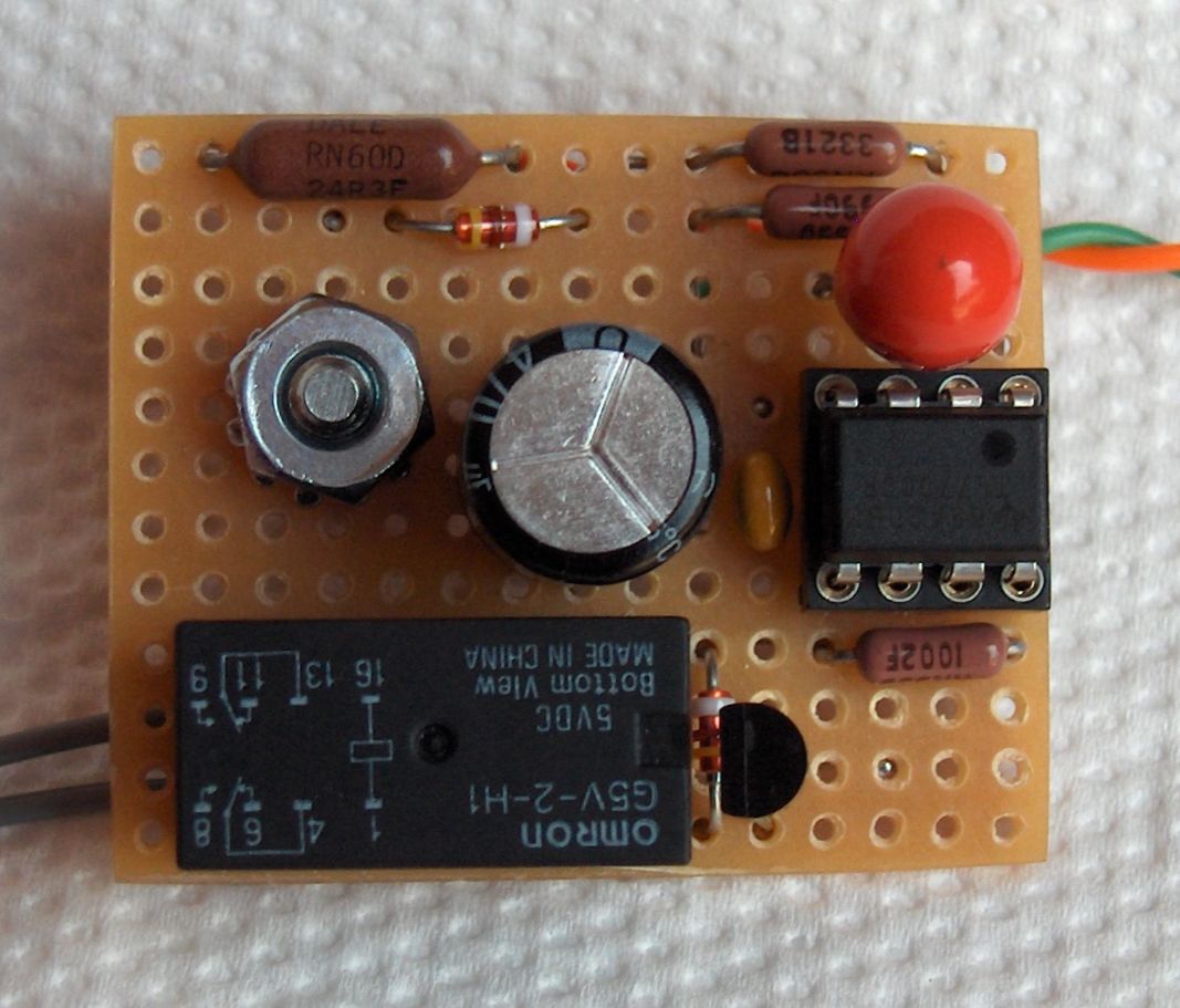
Photos
Click on the small photos for a full-size photo in grisly detail.