A Power Opamp Driver and Bias Supply PCB, and class-A2 experiments
(Note that the photos are hyperlinked to full-size photos in grisly detail)
I've wanted to try using a high-voltage power opamp (like the TI OPA452) to drive the grid of a tube for some time. Though the voltage swing is a bit limited (about +/-36V for the OPA452), it can source some current, so it seems like an interesting driver for class-A2. To facilitate this, I built a small PCB with a power opamp, as well as a small PCB to power it. Details on the boards are below.
My thought was that I should be able to use this driver and a cheap transmitting tube driven in class A2 to make a cheap, simple amp. I have tried a number of tubes, but have more work to so.
So far I've only tried single-ended designs. I will eventually try some push-pull designs - you can set up one power opamp as inverting, and the other as non-inverting, and feed them the same input to make a push-pull amp. But I have not tried it yet...
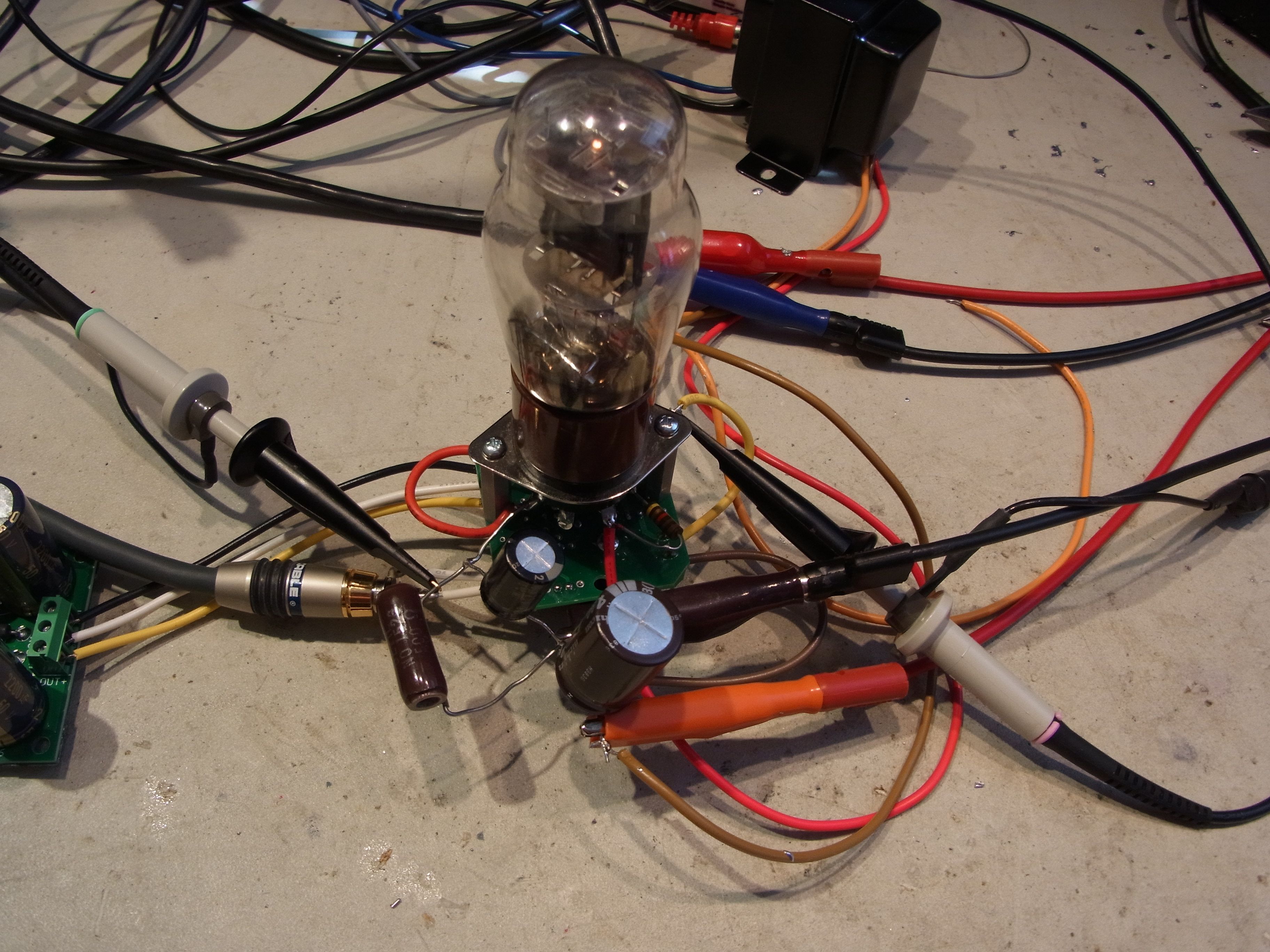
I tried the 2E26 and 1626 tubes in single-ended. The 2E26 worked fine, but really I got very little advantage over biasing in class A1. The 1626, however, worked pretty well in A2. The usual power output from this tube in A1 (as in the "Darling" amps) is about 750mW. Running in A2, I got almost double that - 1.4 watts at 5% THD. The opamp was hitting clipping at this point. 1W THD is about 2%. I used cathode bias (500 ohms) and a low B+ of 200V. This set the operating point at Vp = 174V, Ip = 30mA (just a little over the 5W limit).
Push-pull should get about double this or higher, if you push into AB2.
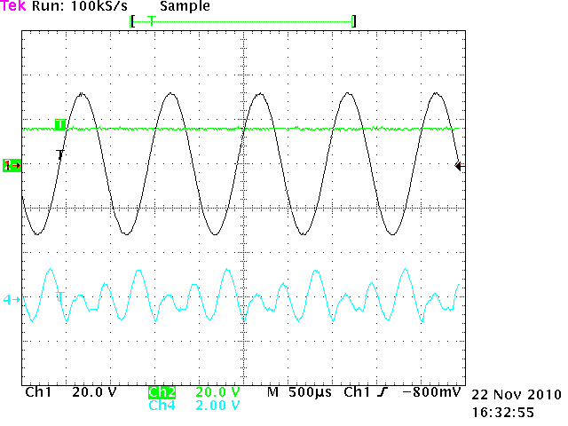
The scope shot below shows the grid (black) and cathode (green) of the 1626 tube. You can see it is running well into A2 operation, with the cathode sitting at about 15V and the grid swinging between ~-12V and +30V. The blue (cyan?) trace shows the distortion residual from the audio analyzer.
An FFT at 1W shows a mix of harmonics...
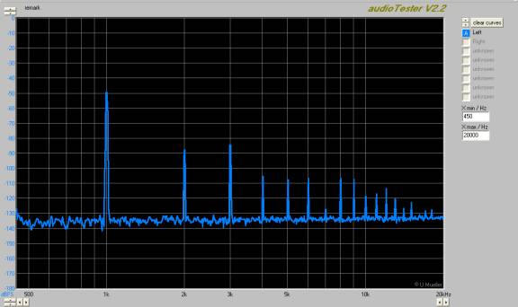
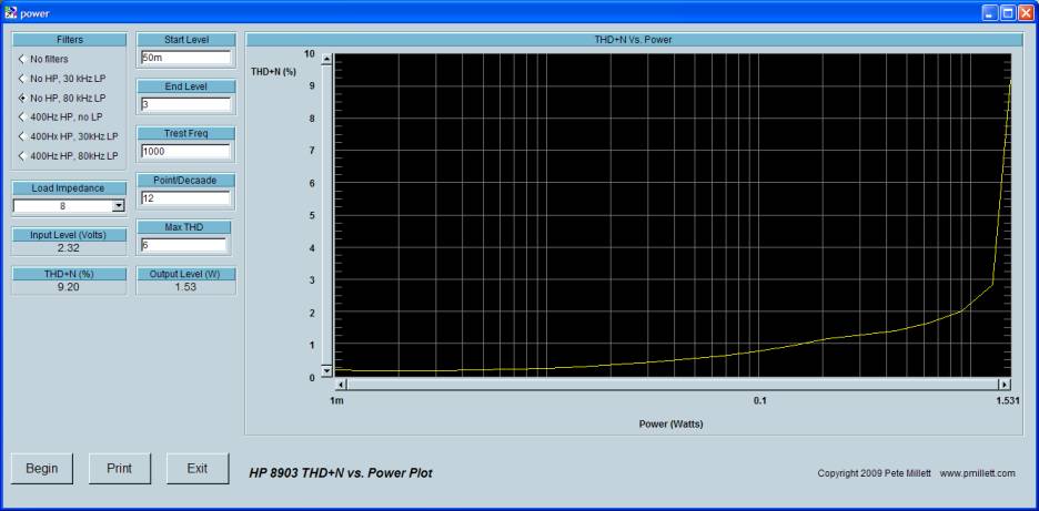
...and a power vs. THD plot looks pretty conventional, except you can see a slight flat spot at 0.2W. This is where the amp enters A2. I expected a bump UP in THD, but the THD actually flattened out a little in A2. As Spock would say: Fascinating...
That's all for now, if I ever get time I'll try push-pull...
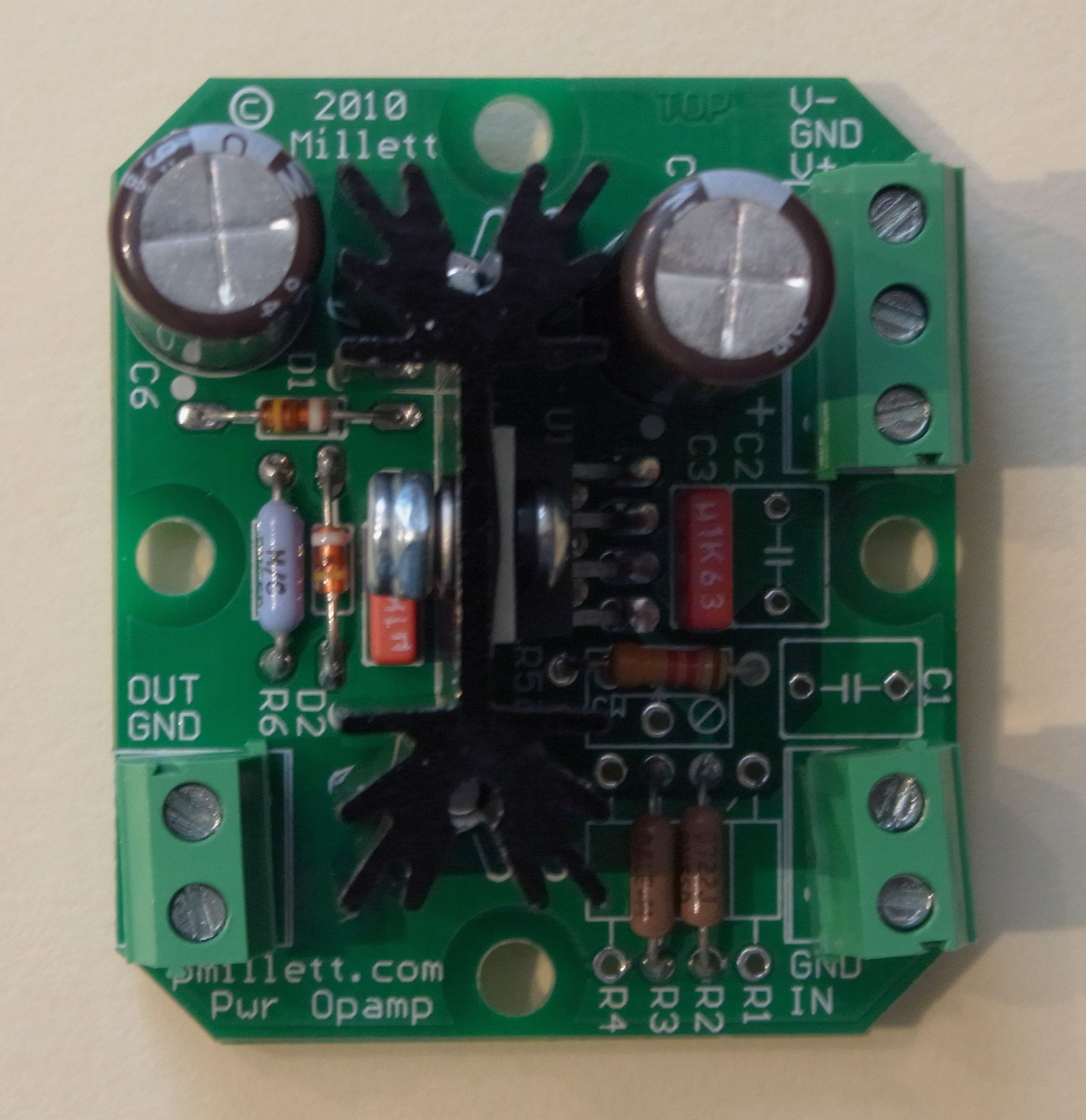
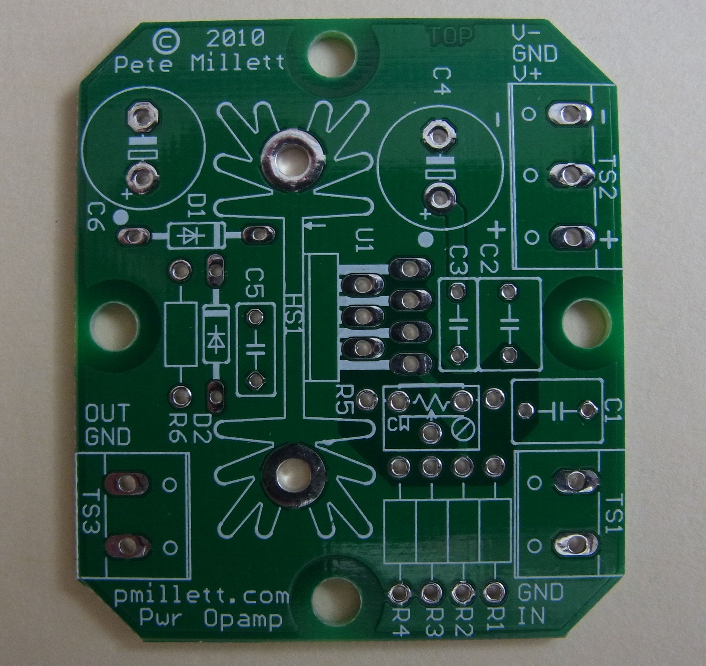
The power opamp PCB
To facilitate the experiments, I made a couple of small PCBs - one to carry a TO-220 package power opamp, and one to provide a small DC power supply. Here's the power opamp board schematic (or download a PDF file):
Basically just the opamp, decoupling caps, and positions for resistors and capacitors so you can make an inverting or non-inverting amp, and add some compensation (the caps) if needed. I made the PCB small, and positioned holes so you can mount it on the same holes that you use for a tube socket (in the picture above, the PCB is mounted to an octal socket). The PCB supports power opamps in a 7-pin TO220 package, including the +/-40V 50mA OPA452 and OPA453, and the +/-30V OPA547 (500mA) and OPA548 (3A).
I made some measurements of the OPA452 itself. I was surprised to see that driving 20V RMS into 1k, the THD was under 0.005%, and was mostly second harmonic. that's pretty good for a power opamp! Made me think that a pair of these would make a pretty good headphone amp. Maybe switch to the OPA547 to drive 32 ohm headphones. Or use the OPA548 and drive speakers! it should work well as long as you don't get the thing too hot - the on-board heatsink is not huge.
The board is so simple, I have not made a detailed BOM. If you want to build one, here are a few notes:
I'll sell my extra PCBs on eBay
All resistors are 1/4W.
The heatsink is a 1.38" x 0.5" footprint, like the Aavid 513102B02500G.
R5 can be a fixed resistor, or a trimpot. They occupy the same PCB space so only one or the other is installed.
Look at the notes on the schematic (PDF version) for details on which parts to install for which configuration.
Terminal blocks are standard 5mm or 0.2" centers, or you can solder wires in the holes.
The power supply PCB
The power supply is simple, designed so you can stuff it as a single-ended or bipolar (+/- voltage) supply. Seemed like a useful thing to have around, you could use it as an opamp supply (like here, I was generating +/-35V or so), or as a negative bias supply. It uses a 12 watt PCB-mount "flat" transformer. Here's the schematic (or a PDF file):
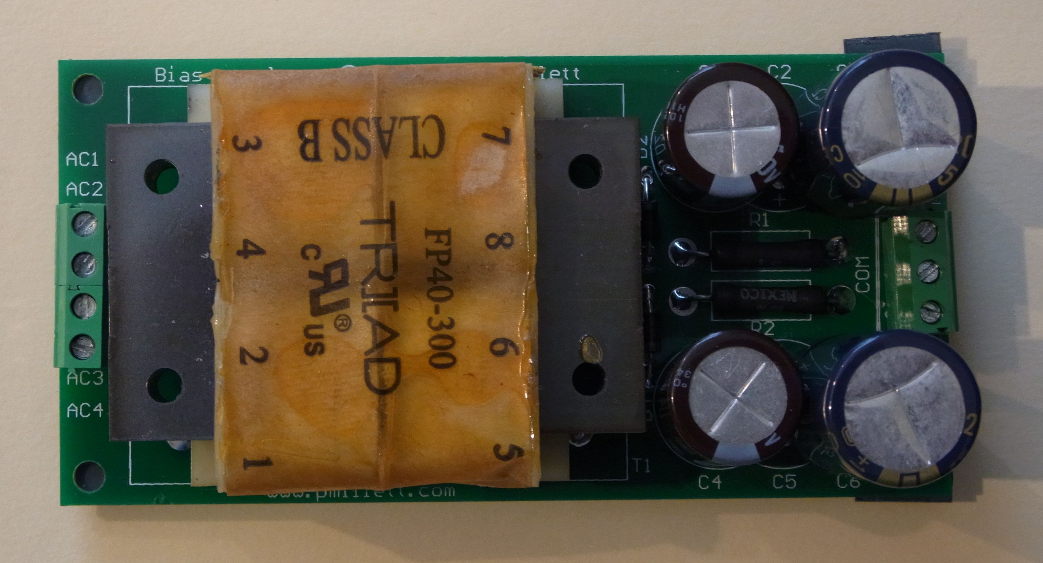
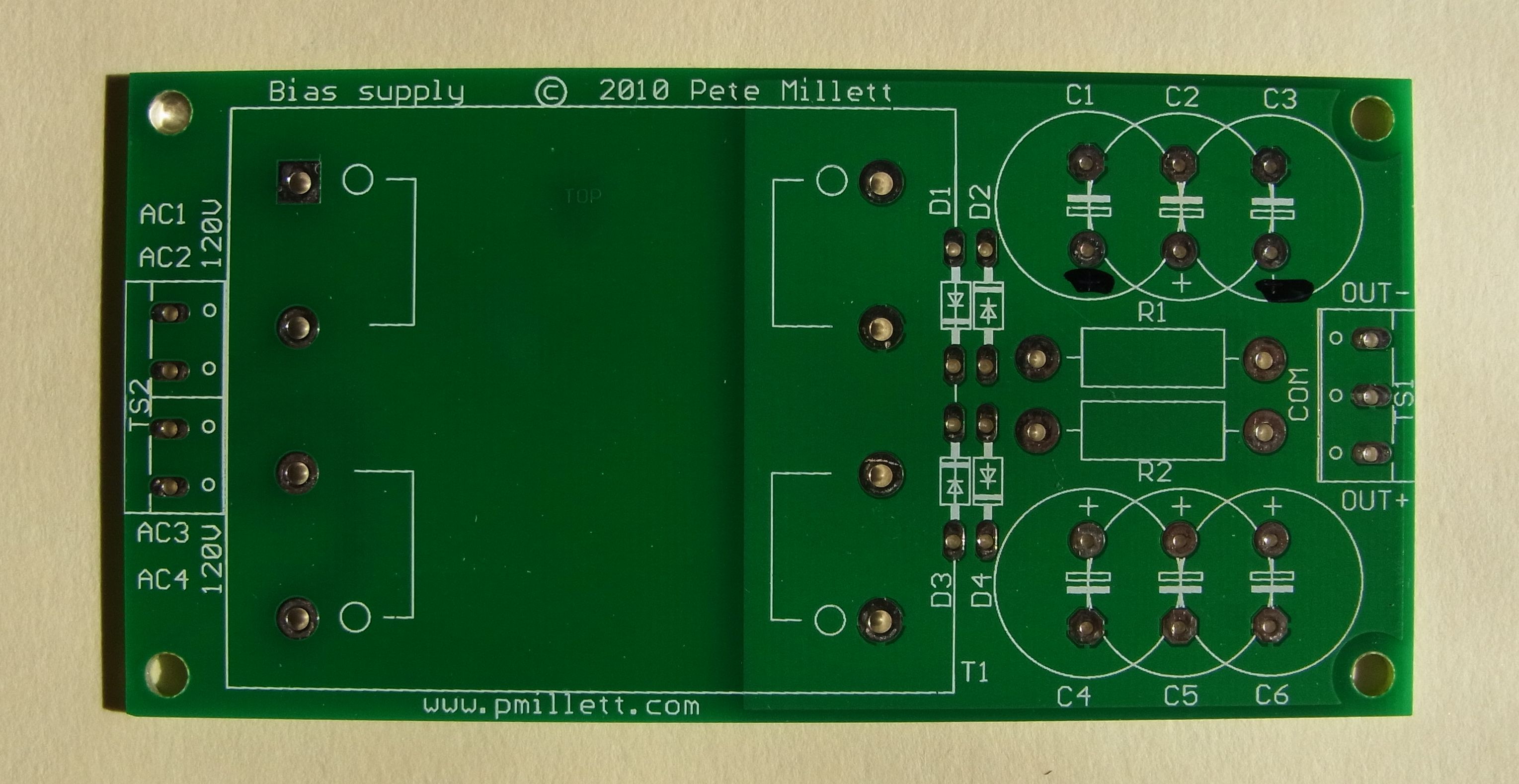
(Yes, I screwed up the polarity on C1 and C3 - see the magic marker? At least I realized it before there was an explosion...)
As above... This board is also so simple, I have not made a detailed BOM. If you want to build one, here are a few notes:
I'll sell my extra PCBs on eBay
You can use tools like PSUD II from Duncanamps to figure out what transformer voltage and what value caps and resistors you need.
R1 and R2 are 1W wirewounds.
The transformer is a 12VA flat transformer, like the FP40-300 from Triad, or similar parts from Signal, Hammond...
Install C2 and C5 for a unipolar supply, C1, C3, C4, C6 for a bipolar (+/-) supply.
Note the silkscreen error on the polarity of C1 and C3!
Connect the inputs in series for 240V, parallel for 120V. See the transformer datasheet for instructions if its not clear.
There is no fuse on the board - for safety, you need to insert one somewhere between the wall socket and the transformer.
Terminal blocks are standard 5mm or 0.2" centers, or you can solder wires in the holes.