The 26A7 tube - and a low voltage line stage
This project started with ETF.25.
At ETF (European Triode Festival), we have a "shoot-out" every year. Something is chosen for people to build, and during a semi-blind listening session, the best sounding whateveritis is selected through rounds of AB listening tests. No, it is not scientific and is done just for fun.
The ETF.25 shootout was for line stages. Specs included triodes as the amplifying device (or triode connected whatevers), a minimum of 6dB gain, and a few other specs typical of a line stage.
I built a simple, low voltage, lightweight (so I could carry it to Europe!) line stage. And for the first time in 23 years... I won!
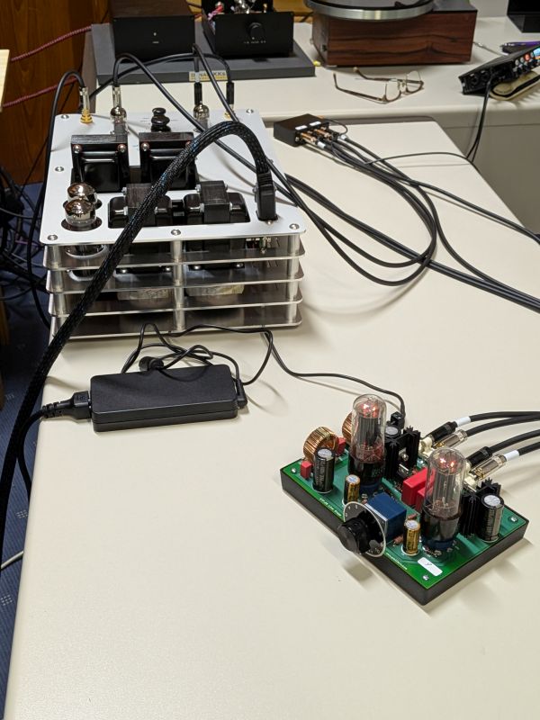
What I built measures well, and most agree that it sounds good. And of course, being me, it is NOT conventional. Here are the two shootout finalists: mine (the tiny thing on the right) vs. a beautiful build by Eddie Pletka:
The 26A7 tube
I ran across the 26A7 tube quite some time ago. I found it interesting... it is a dual pentode that was designed as an audio power amplifier to drive a speaker, running only from a 26V power supply. Here is a datasheet: http://www.tubebooks.org/tubedata/hb-3/receiving-type_industrial_tubes/26A7-GT.PDF
The only place I can find that the 26A7 tube was used was in the US military R-392/URR radio receiver. This 25-tube monster was a general coverage HF receiver made from about 1951 to 1962. It is a rugged beast that was used in the Korean war and in Vietnam. Google can tell you more about this radio.
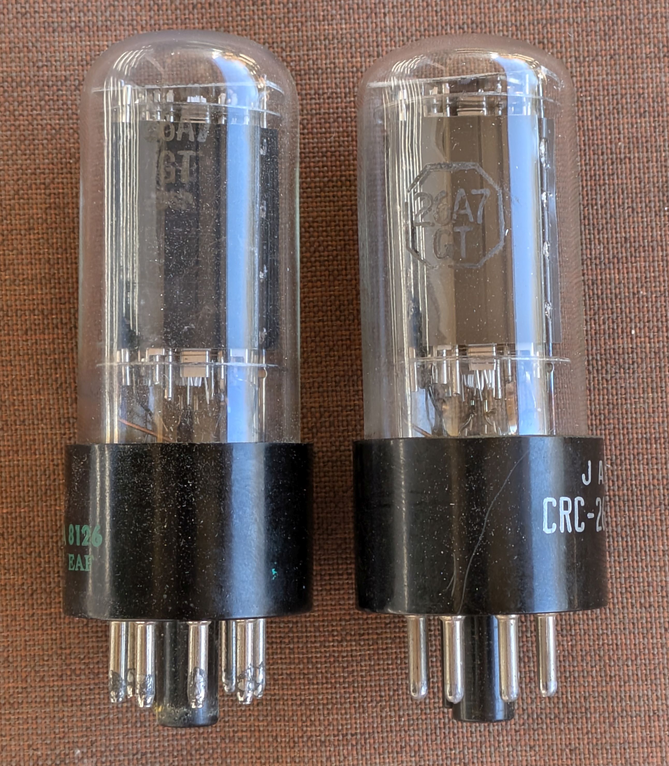
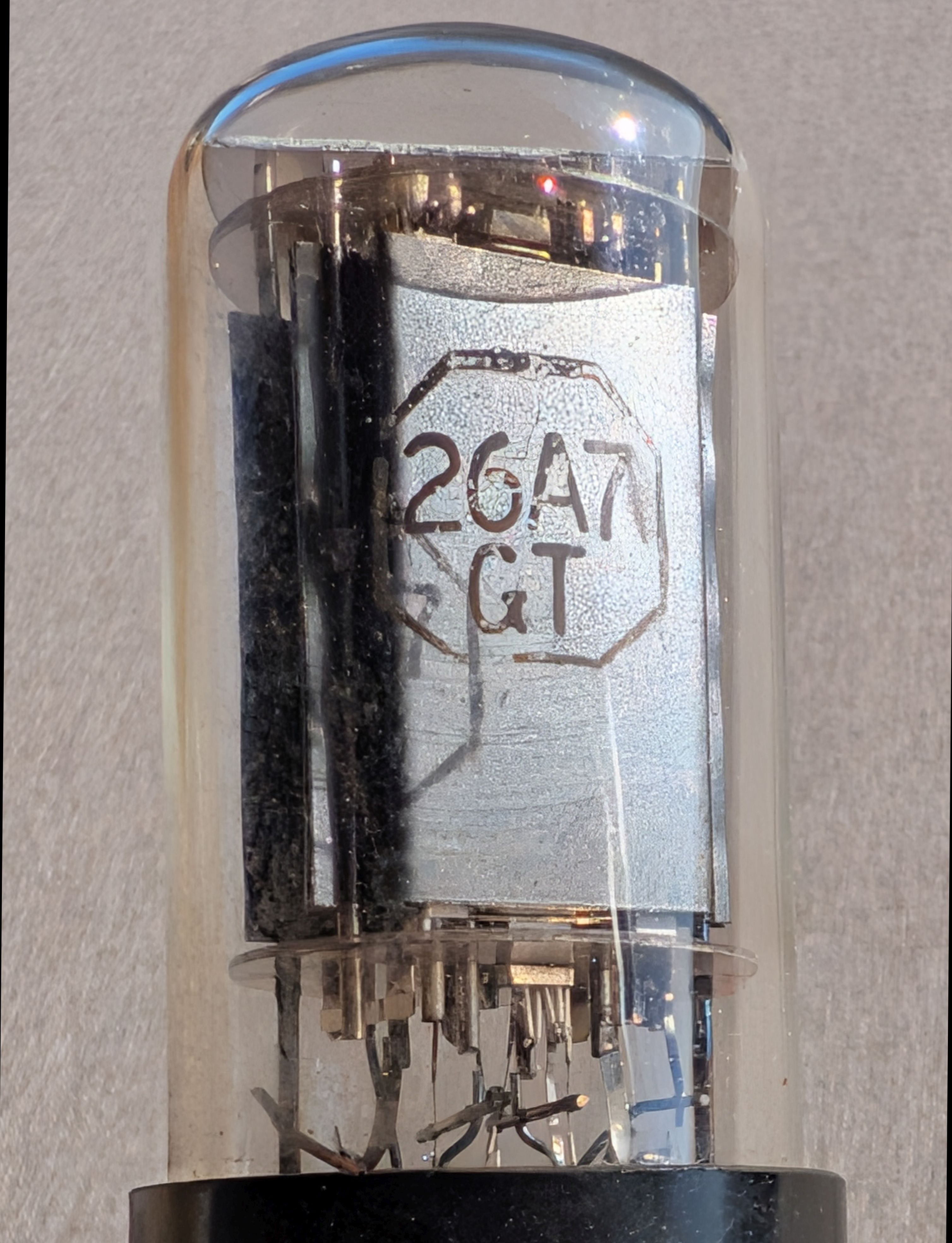
The 26A7 is an octal GT-shape tube. It has a 26V heater that draws 600mA - that's over 15 watts of heater power! That is how they can get enough emission to do something useful at 26V B+.
Here's some pictures (Sylvania branded on the left and RCA branded on the right):
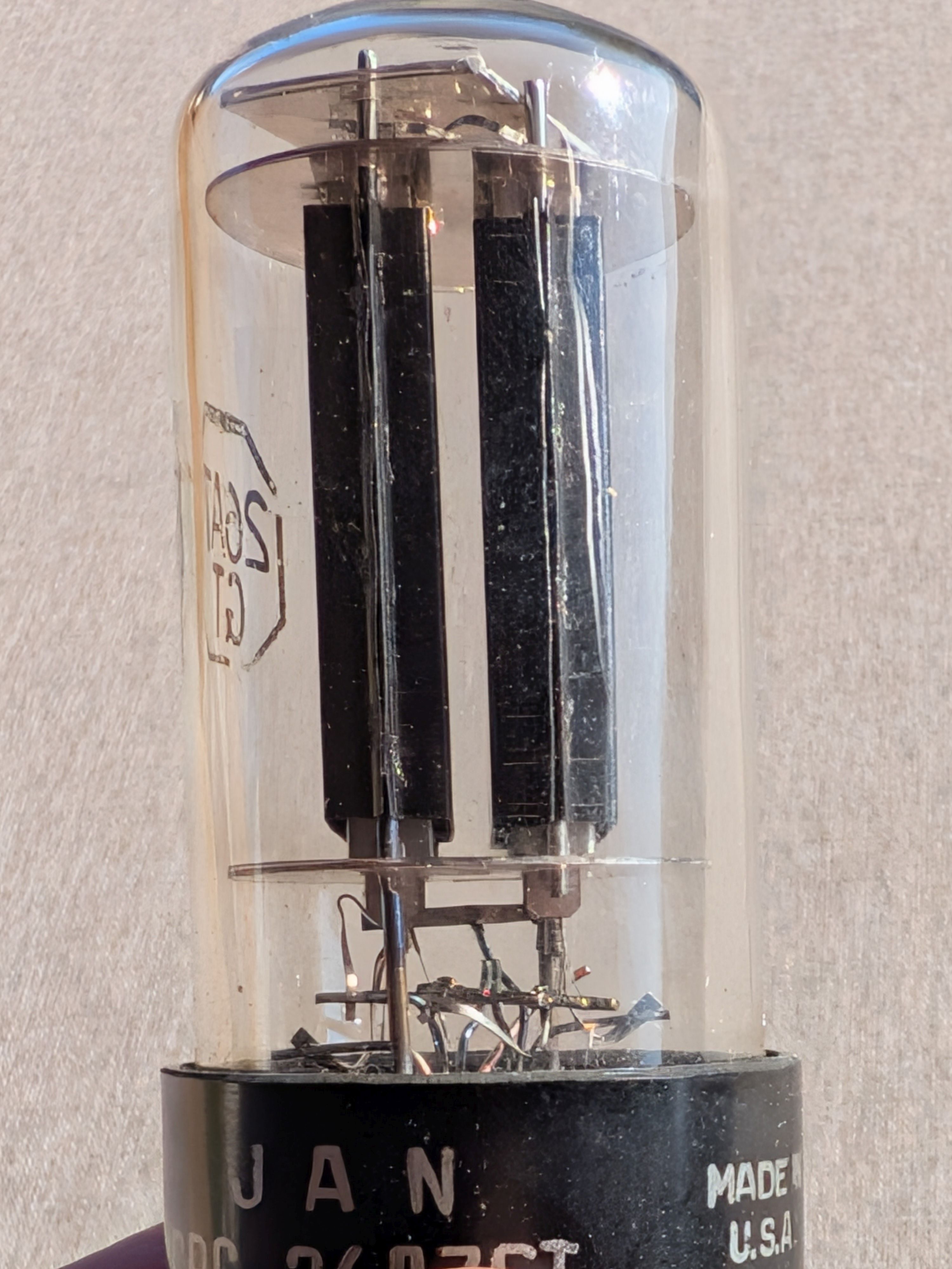
The R-392 was designed pretty much at the end of the vacuum tube era, and was soon replaced mostly with solid state radios. But the US military had stocked thousands of tubes at that point. So these things are readily available, and not very expensive.
So, I got some 26A7 tubes and started experimenting. Long story short that with both sections connected in parallel triode mode (G2 is shared, so G2 is connected to the two plates, and the two G1's are connected together) you get a pretty interesting triode that can run at low voltages:
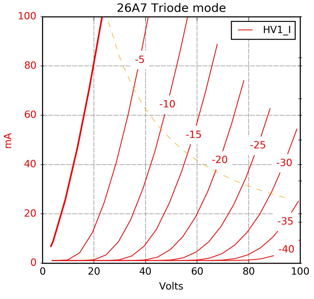
According to my measurements, at a plate voltage of 26V and 30mA plate current, I measure a gm of about 10k, mu of 3, and Rp of 292 ohms.
The line stage
I loaded the parallel triode connected 26A7 with a CCS. The power supply is a 54V desktop switcher, so B+ here is 54V. The two 26A7 heaters are connected in series. Otherwise this is pretty conventional:
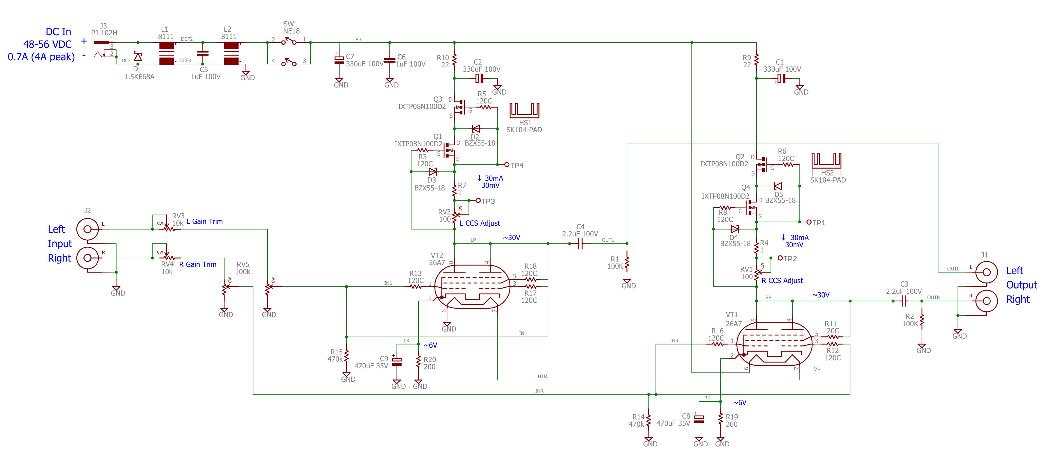
Here is a PDF schematic
I built this on a small PCB that sits in half of a plastic enclosure:
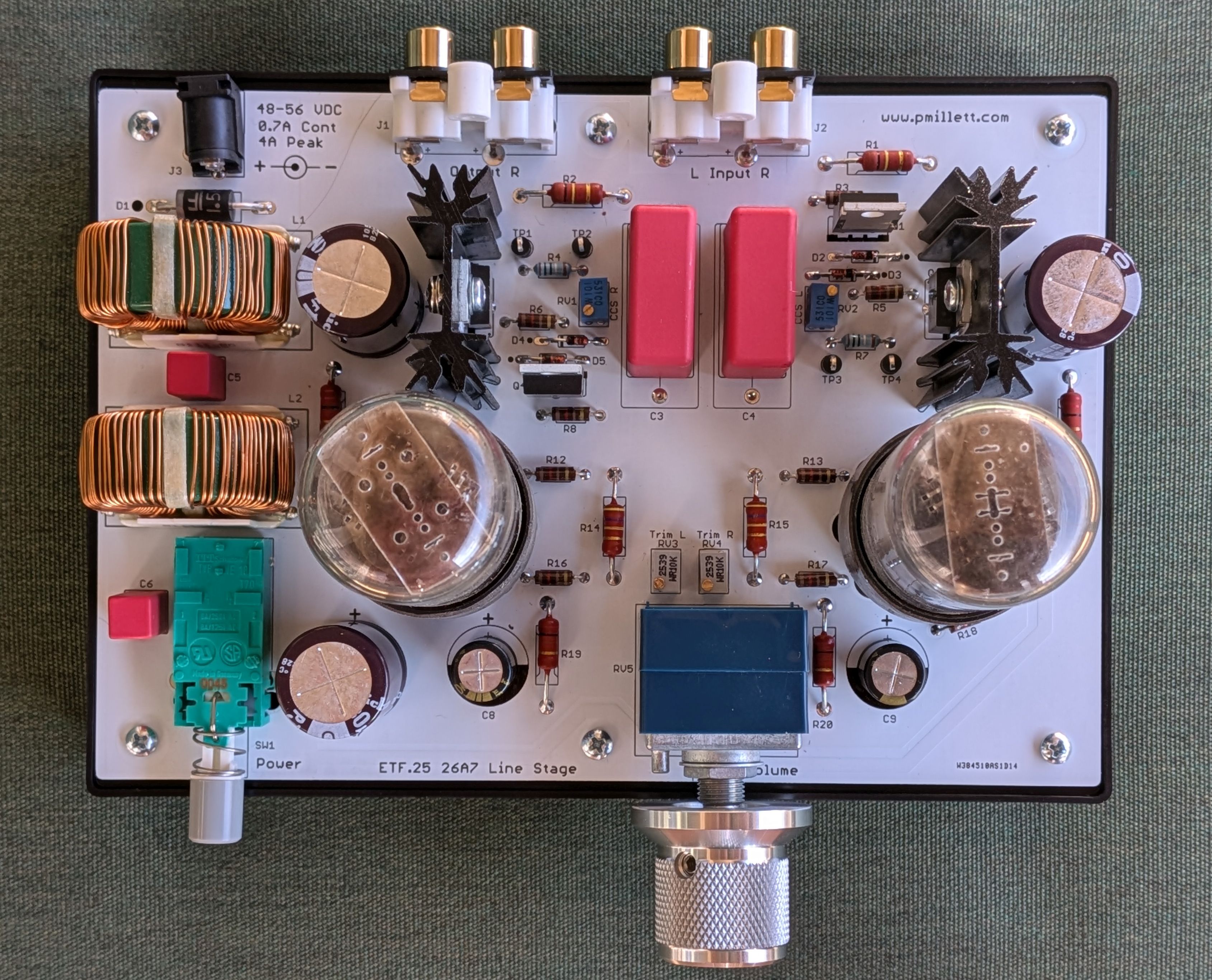
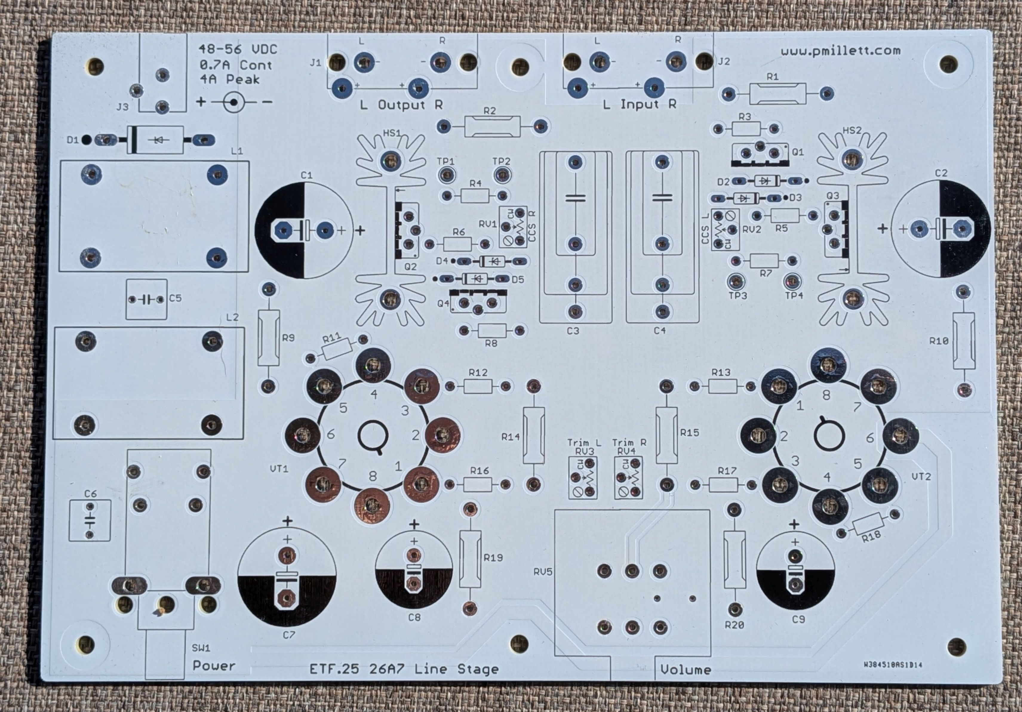
Here is a PDF of the PCB showing dimensions
Here is a BOM (parts list) in XLS or PDF format
Note that I specified a fairly high power desktop switching power supply. The cold resistance of the two heaters in series is 12 ohms... that means at power up it will draw over 4A. The supply I used is OK with powering up into the cold heaters if you switch it on via the AC input - it just thinks it's charging a bunch of capacitance. But if you switch the DC side (like I did here with a power switch on the board), the supply thinks you have shorted the output so it shuts off. But it goes into a retry mode ("hiccup" mode) turning on and off. Eventually it gets the heaters hot enough that the resistance increases and it stays on. This doesn't seem to cause any issues, but you should be aware of it.
You can of course use a different power supply, including a normal linear supply. Unregulated is OK, but the output should be within +/-5% of 52V when loaded with 700mA. Basically between 48V and 56V.
I also designed a second PCB that removes the connectors and volume control. I did this for people who want a more conventional preamp, with chassis mounted connectors, input selector, and volume control. Note that the parts are all on the same side as the tubes. It is possible to build it with all the parts other than the tubes on the bottom side, so you could stick the tubes through the chassis. Of course you need to watch the polarity on the electrolytic caps and diodes. The only parts that aren't mechanically symmetrical are the MOSFETs - you have to be careful that pin 1 is correct. That means that the center pin is bent backwards instead of forwards. It also means that the heatsink I used won't fit. These FETs dissipate less than a watt, so you can use a different heatsink that just mounts to the FET and not the PCB.
Here is what this version (I'm calling it "26A7" instead of "ET25") looks like:
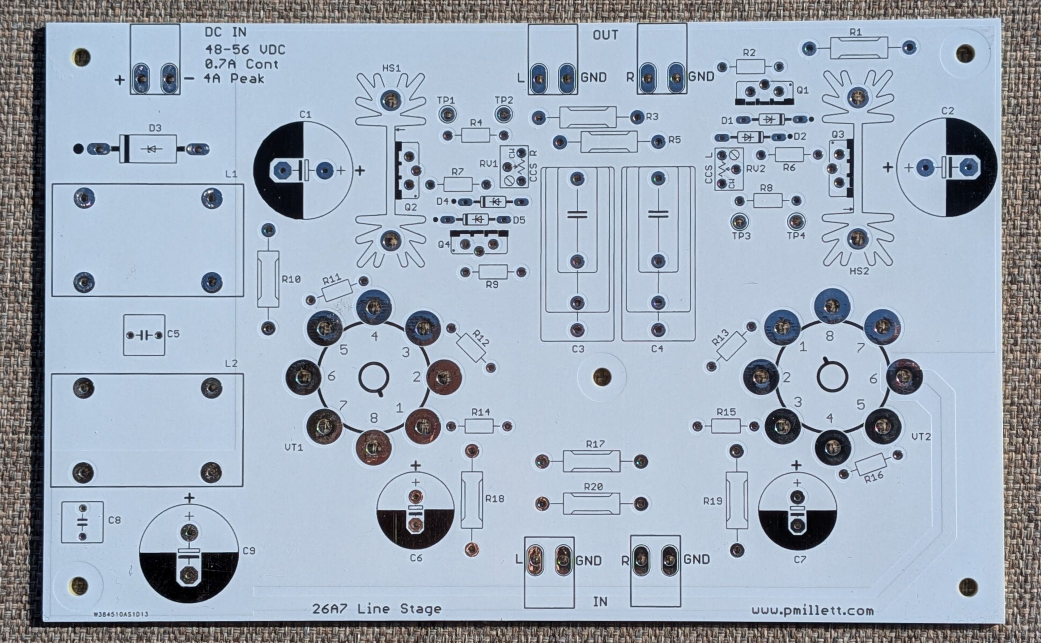
And a PDF showing dimensions
Parts list (BOM) in XLS or PDF
Schematic in PDF (basically the same as above without connectors or volume control)
Measurements
I made a full set of measurements using the APx515B... Unless otherwise noted these are at 1V RMS out, 100k load, and 1kHz.
Here is a summary:
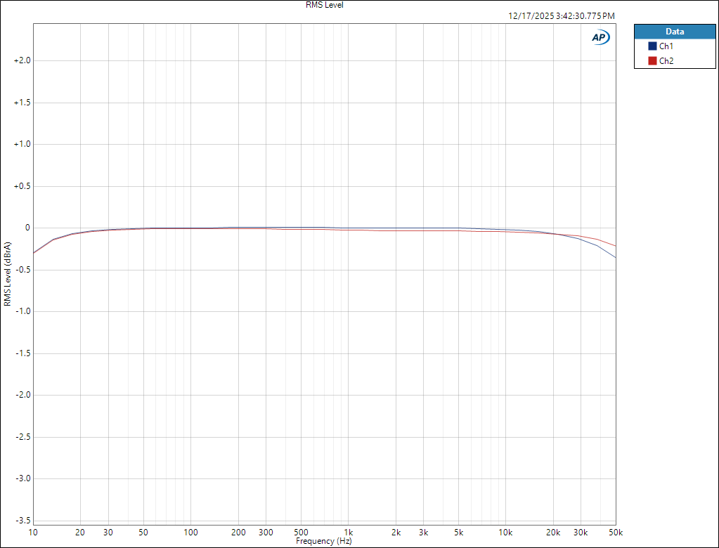
Frequency response - within 0.5dB 10Hz - 50kHz. Note that this is loaded with 100k. At lower loads you will start to see rolloff at low frequency due to the output coupling capacitors. For loads under 10k or so it would be best to increase the 2.2uF coupling caps to something bigger. If you want to drive 600 ohms best use 20uF or so.
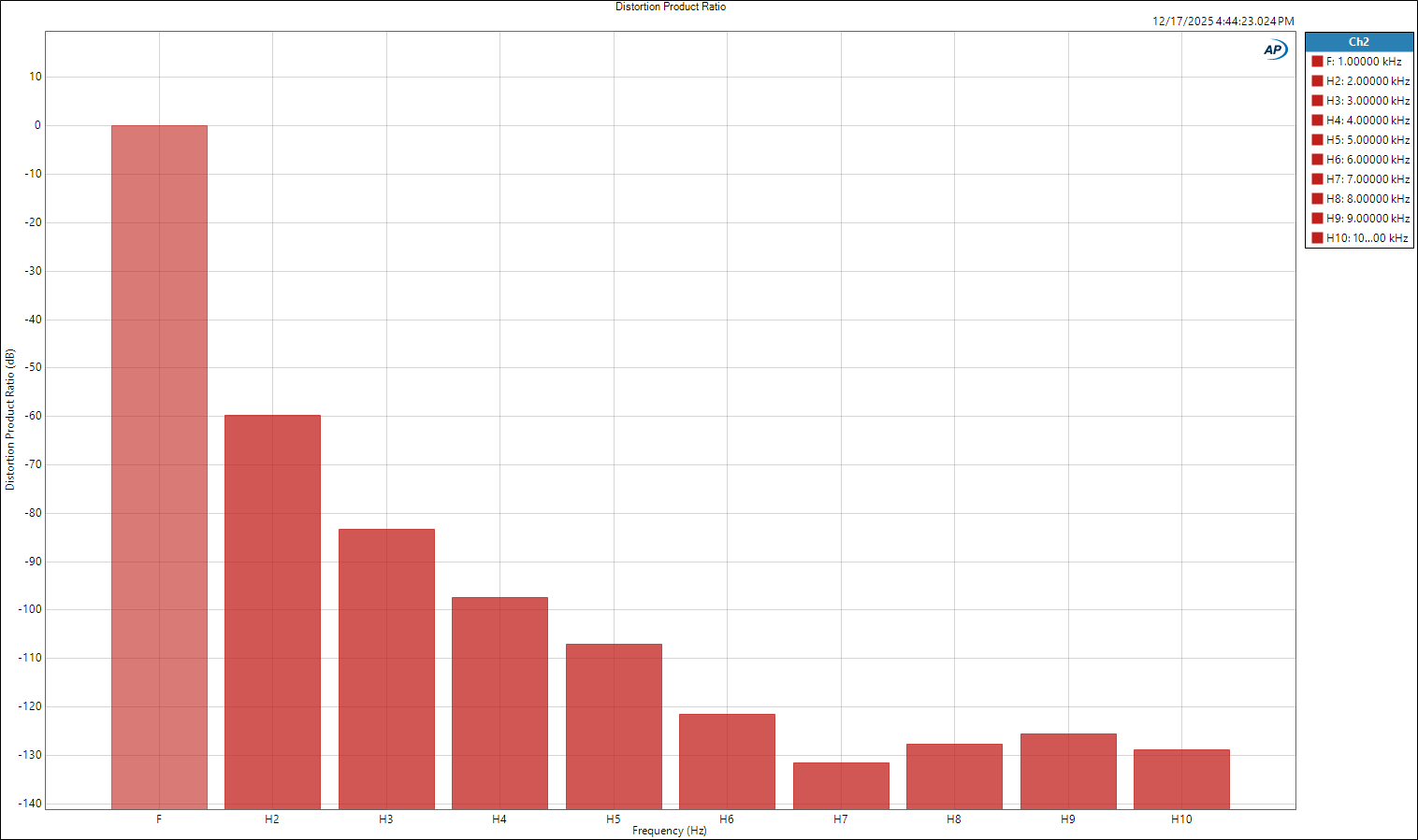
FFT (1V TMS, 1kHz)
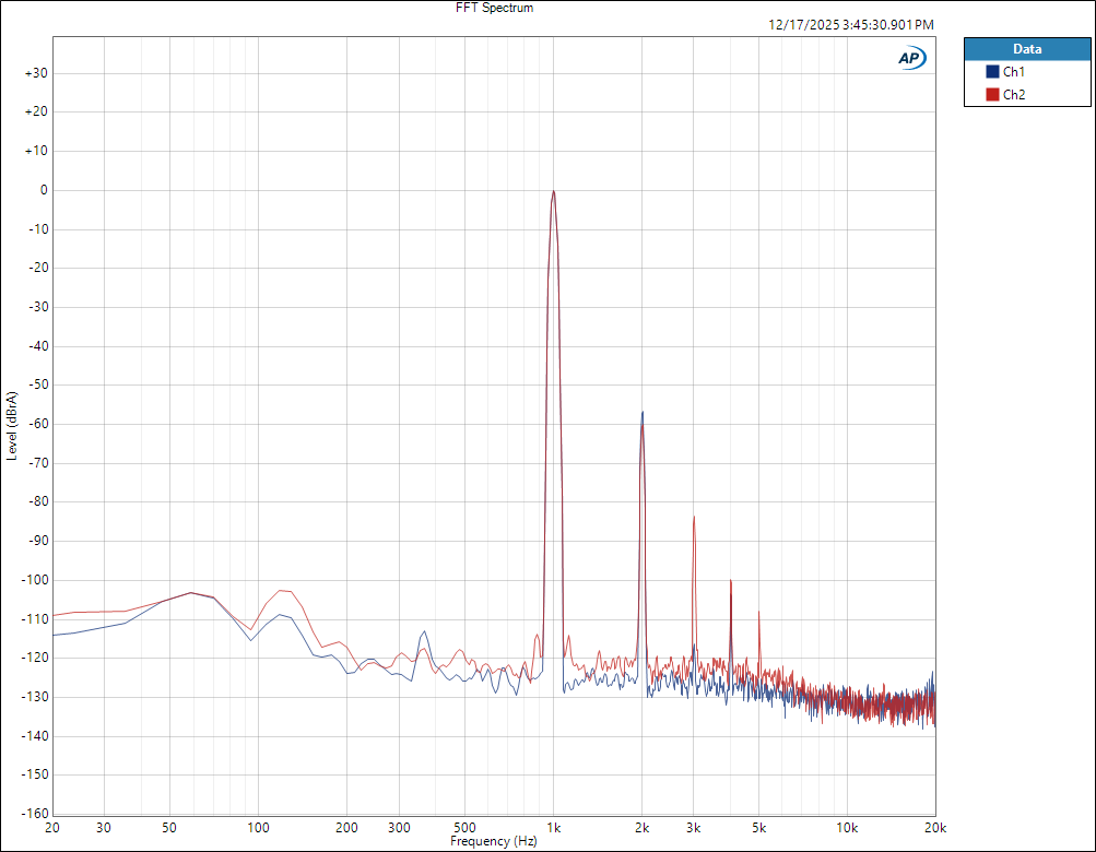
Distortion products (sort of another way of looking at the FFT). Anything past H6 is in the noise.
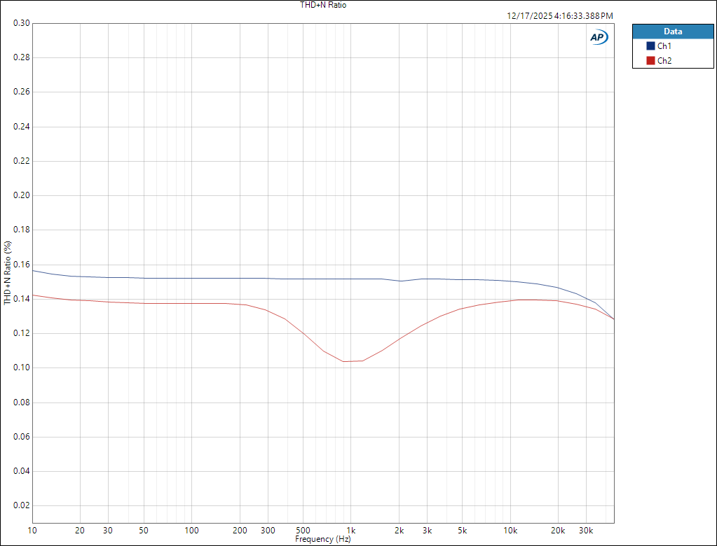
THD+N vs. frequency (1V out). Basically flat (note the scale). I have no idea why one channel shows a dip around 1kHz. Could be a measurement artifact, or ??? I made no attempts to swap or select tubes, these are just 2 pulled from the box.
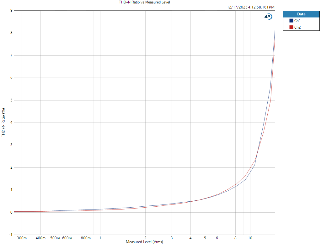
THD+N vs. output level (1kHz)
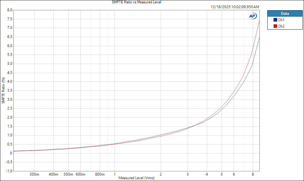
SMPTE IMD vs. output level
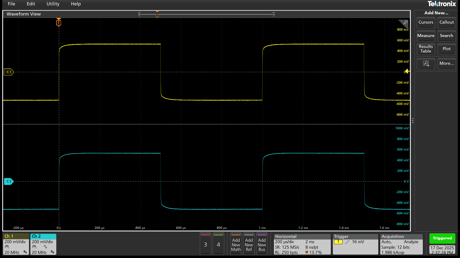
Square wave response 1kHz, 20MHz bandwidth