"Fatboy" 300B push-pull amp
The last few amplifiers that I've designed used pentodes and lots of NFB to get low distortion.
So I decided to go to the other extreme: how low distortion could I achieve with no negative feedback of any kind. The result is the "Fatboy" 300B amp - named as such because, like me, it is a tad overweight.
Amp Design
The circuit design is old school: Choke-loaded triode direct coupled to DHT driver, transformer coupled to the push-pull 300B output tubes. I used Tango NC-14 interstage and FX40-5 output transformers, which I've had around for a while. Since there is no NFB I'm sure you can use other iron that is more available now. You might need to tweak the driver circuit to optimize it for a different IT, though.
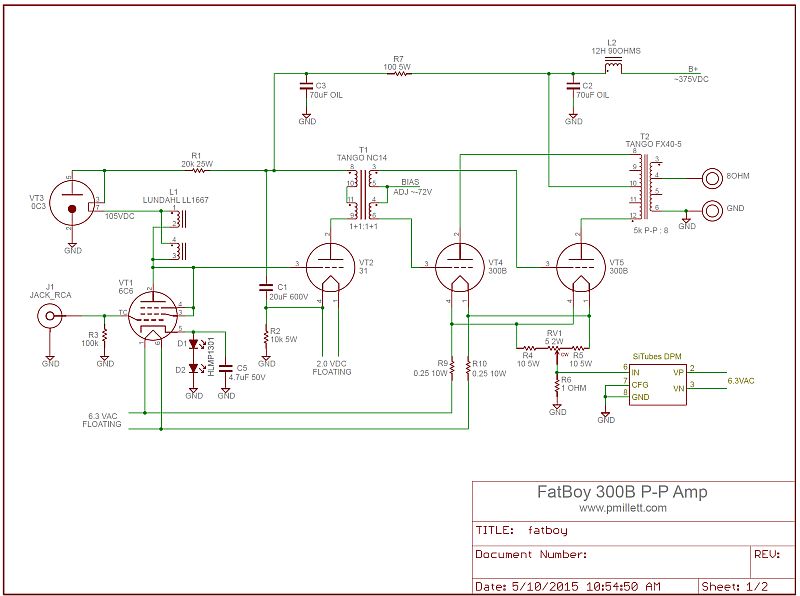
Download a PDF version of the schematic
The choice of input and driver tubes was made experimentally. No distortion cancellation going on here (other than the P-P 300B pair) - I tweaked each stage individually for the lowest possible distortion. That's how I wound up with some uncommon tube choices.
The 6C6 is essentially a 6-pin version of the 6J7, which is the top cap version of the 6SJ7. OK, purists, you can claim that using a pentode in triode connection is actually a form of feedback. My argument is that it's just a different way of building a triode! In any case, the 6C6 measured better than the 6J7 and 6SJ7. I don't know why. BTW, a 6SN7 measured well here too, but didn't have enough gain. I tried some more modern tubes like the 7044 and 5687, but this was the best. The 6C6 is biased with a pair of LEDs. Note the parallel cap - yes, it did make a difference - about 1dB at high frequency.
I'm always cautious about direct coupling, because bias shifts in the first stage can cause big shifts in the second. I avoided that issue here by using choke loading driven from a VR-tube-regulated supply. In this way, the grid of the driver tube pretty much always sits very close to the VR tube voltage, so the bias on the driver (provided by a big cathode resistor) doesn't move much.
The 31 driver is a fairly cheap and unpopular DHT. Designed as an output tube for battery radios that put out a couple hundred mW of audio, its low Rp makes a really good interstage transformer driver. I tried a number of different tubes (including the ones recommended on the Tango datasheet) to drive the NC-14, and this was the best I had.
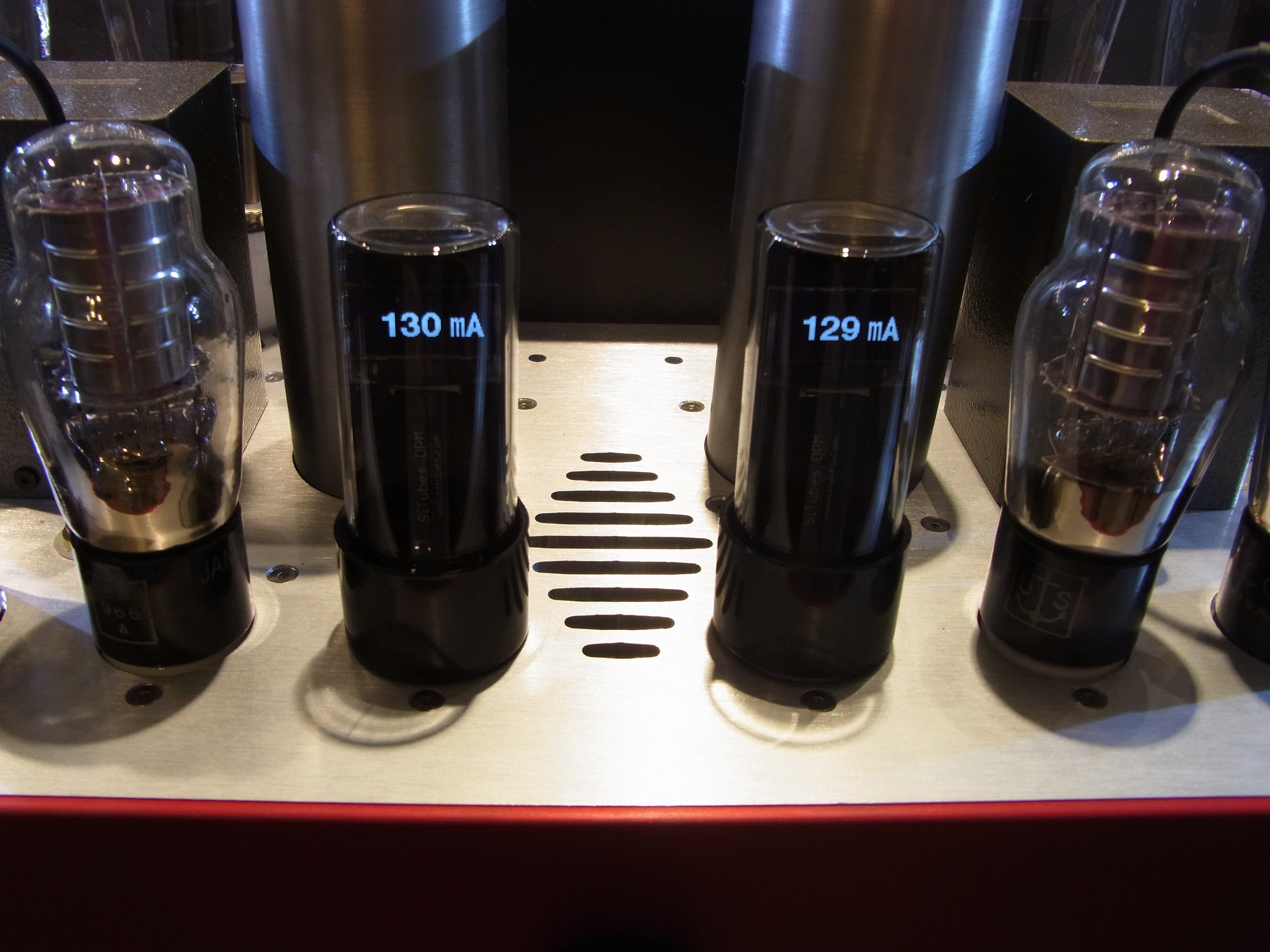
The output stage is a matched pair of 300B tubes. Filaments are heated by AC, with a couple of dropping resistors from the main 6.3V heater circuit. A standard hum balance pot arrangement is used, and a 1 ohm resistor to sense cathode current. That connects to a digital panel meter (SiTubes DPM, a meter-in-a-tube-bottle). There is still a few mV of 60Hz present on the output, but it was not noticeable even with my ear in front of Klipsch Heresy speakers.
So, how did it work? About 0.08% THD at 1W, and only about 0.2% at 10W (1kHz into 8 ohms). But more measurements later...
Power Supply
As is often the case, the power supply is more complicated than the amplifier itself.
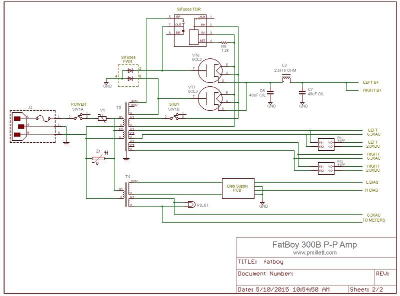
The power supply generates a B+ voltage of around 375V, at 350-400mA for the stereo amp. B+ is generated from a 300V RMS winding on a monster James power transformer that I found in Taiwan. A hybrid bridge is used, using a pair of 6CL3 tubes on the positive side, and SiC Schottky rectifiers on the negative side. A B+ delay relay is inserted in series with one side of the transformer winding to make sure that under all conditions the filaments have time to heat before B+ is applied. The B+ delay relay and the SiC diodes are contained inside octal tube envelopes to make point-to-point wiring easier. For details on these modules, see www.situbes.com.
The filter choke arrangement uses a 40uF oil cap into a large 2.5H, 9 ohm James choke, and another 40uF oil cap. Then, each channel gets another 12H choke and 70uF oil cap (these are shown on the schematic above). The driver is decoupled with 100 ohms and another 70uF oil cap.
Grid bias for the 300B tubes is generated by a shunt-regulated bias supply PCB that I designed. It outputs nominally -72V for each pair of tubes. I didn't include any individual tube bias or balance adjustments, so I am using matched pairs of 300B tubes.
Since the amp uses fixed bias, you really need a way to measure the plate current. For this, I designed some digital "panel" meters that are contained inside class tubes, which mount in an octal socket. This is another product of www.situbes.com. Of course, you can use any meter you'd like, but these look cool :)
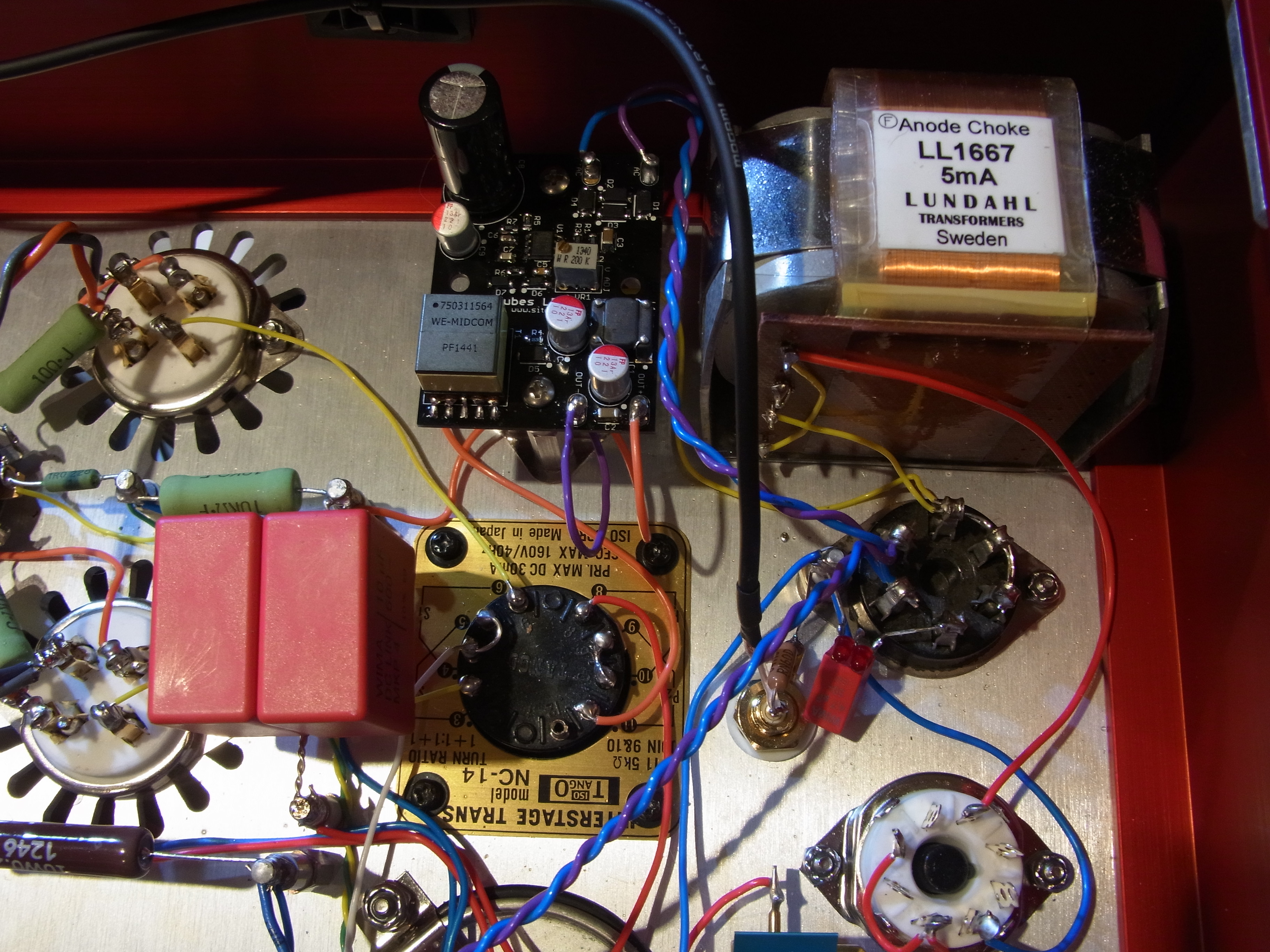
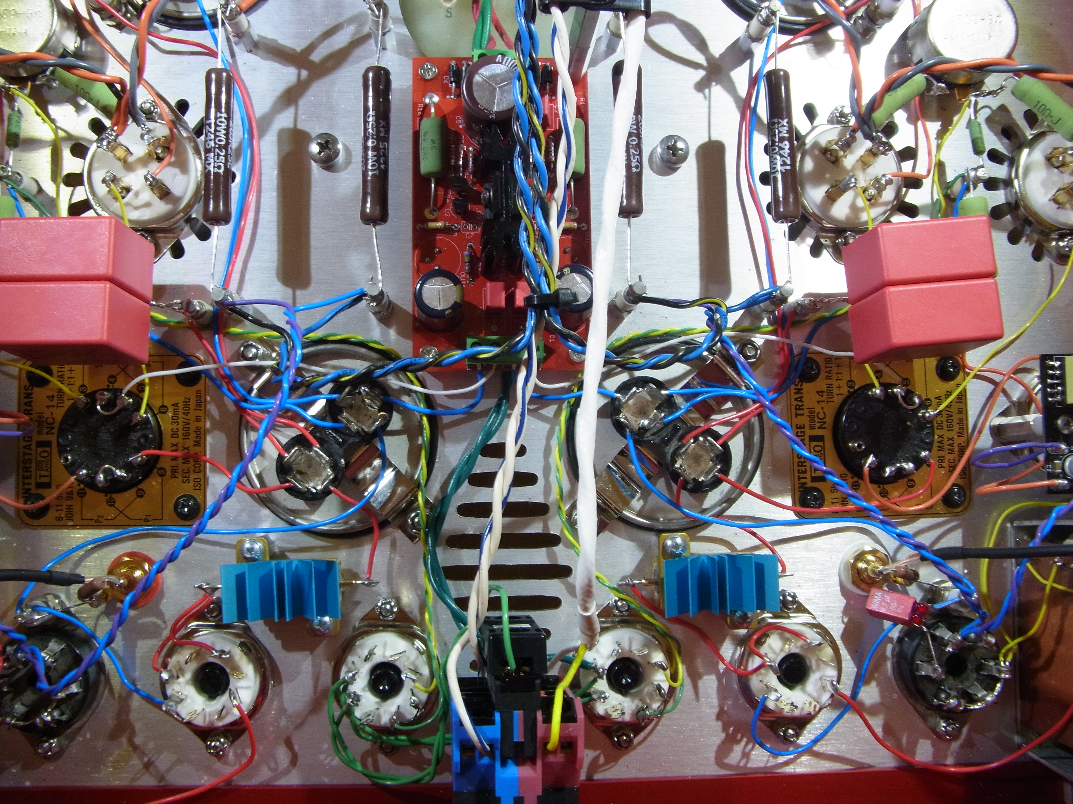
Since the driver is a DHT that is direct coupled to the input tube, the filament has to sit at a fairly high voltage. It really needs DC. You could use a standard transformer/rectifier/regulator that floats to power it. But no! Instead I designed an isolated flyback supply. It sits directly on the back of the tube socket, and convers the 6.3V heater power into isolated 2VDC for the 31 tube. It's the little black PCB that you see in the underside photos below. This module isn't available for sale yet... hopefully soon.
Construction
This thing is HEAVY. The chassis was made by Landfall Systems, and has no problem with the weight.
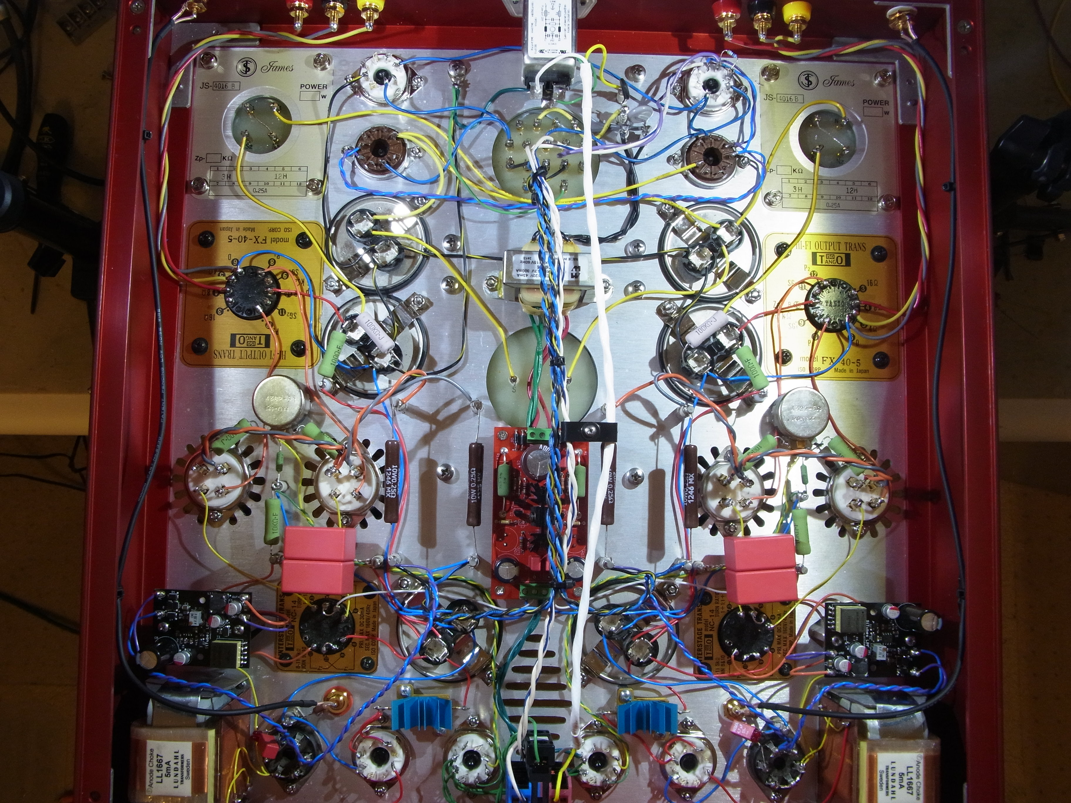
Wiring is standard point-to-point, other than the bias supply PCB and the driver filament supplies.
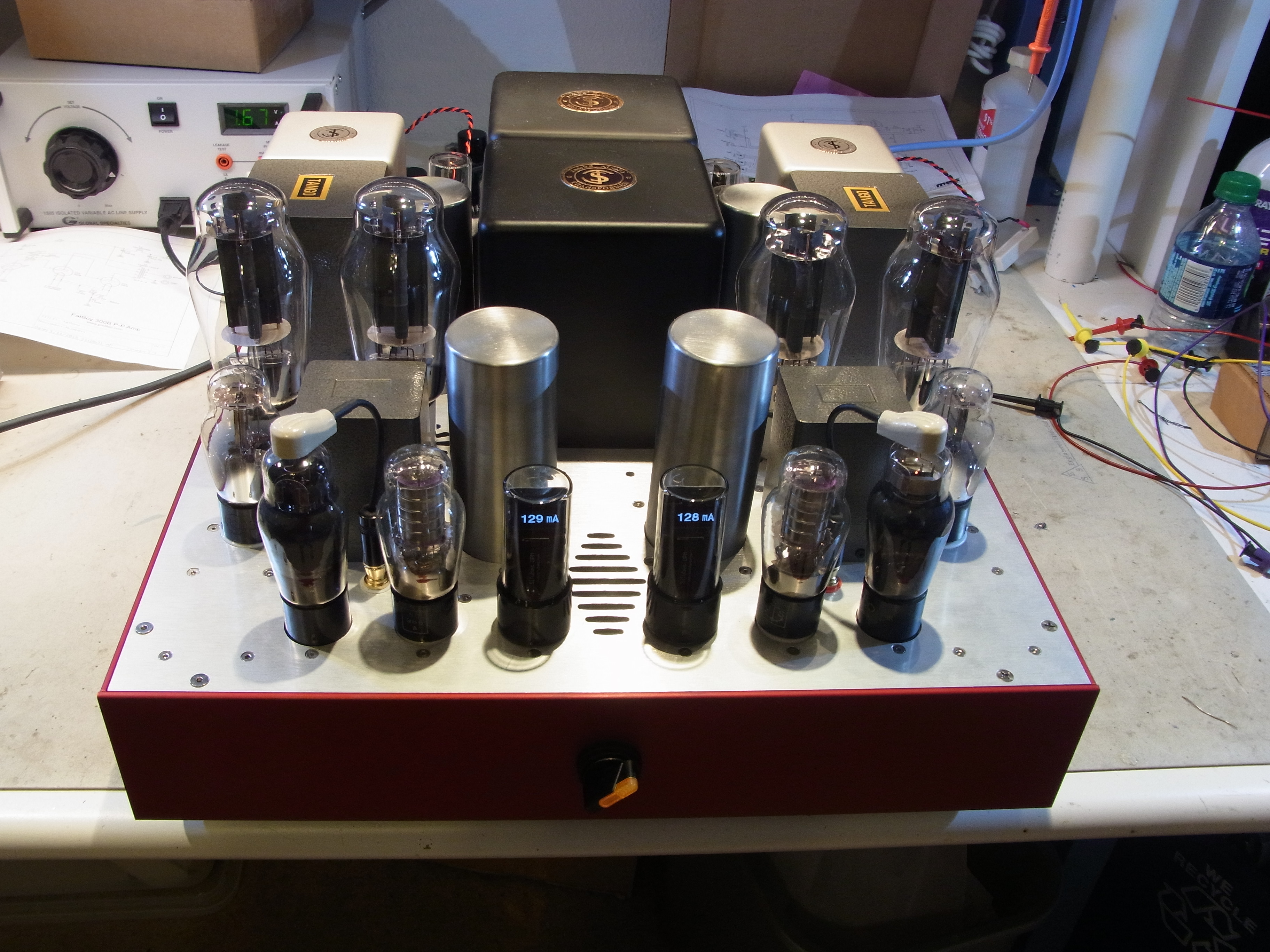
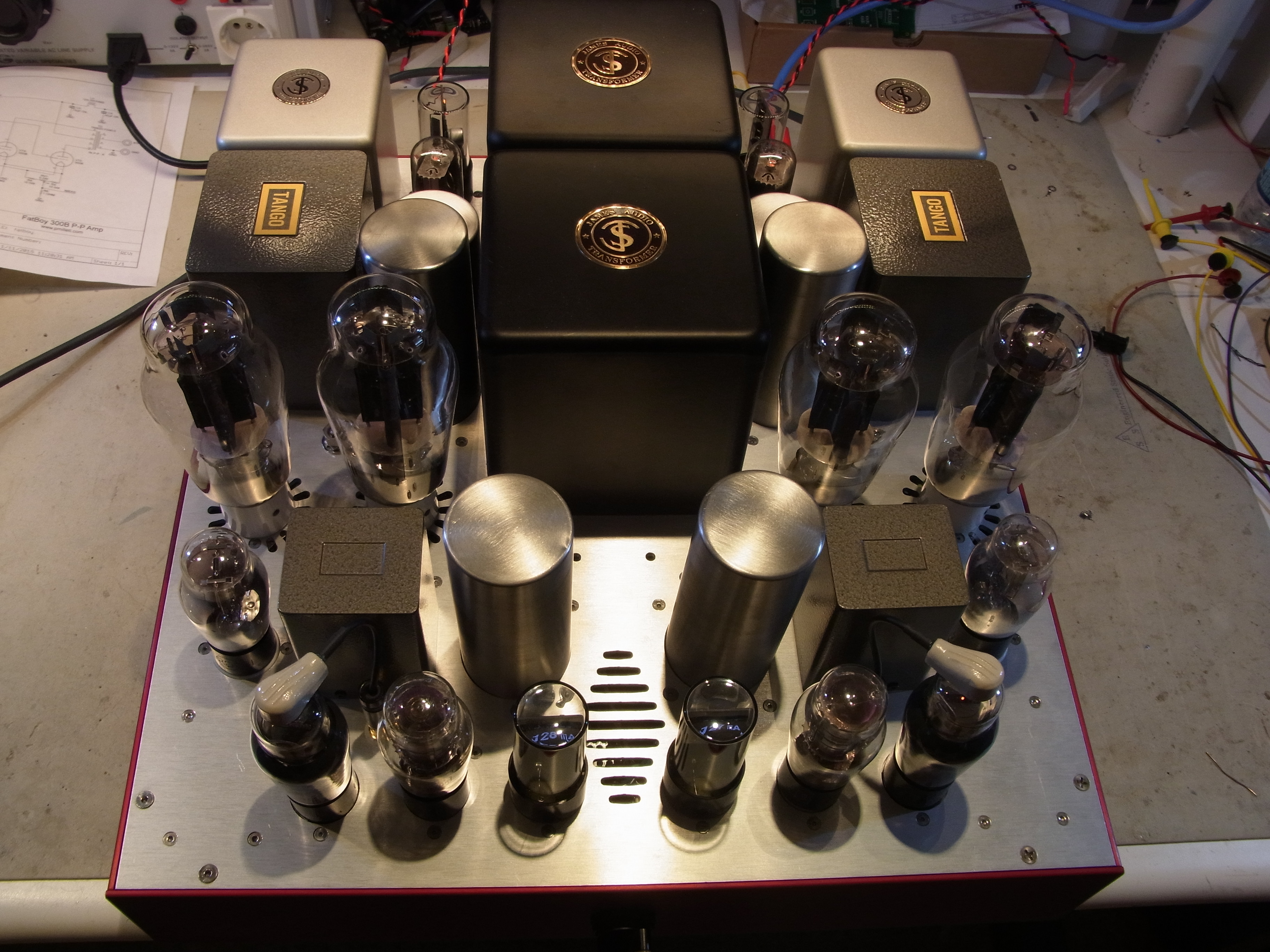
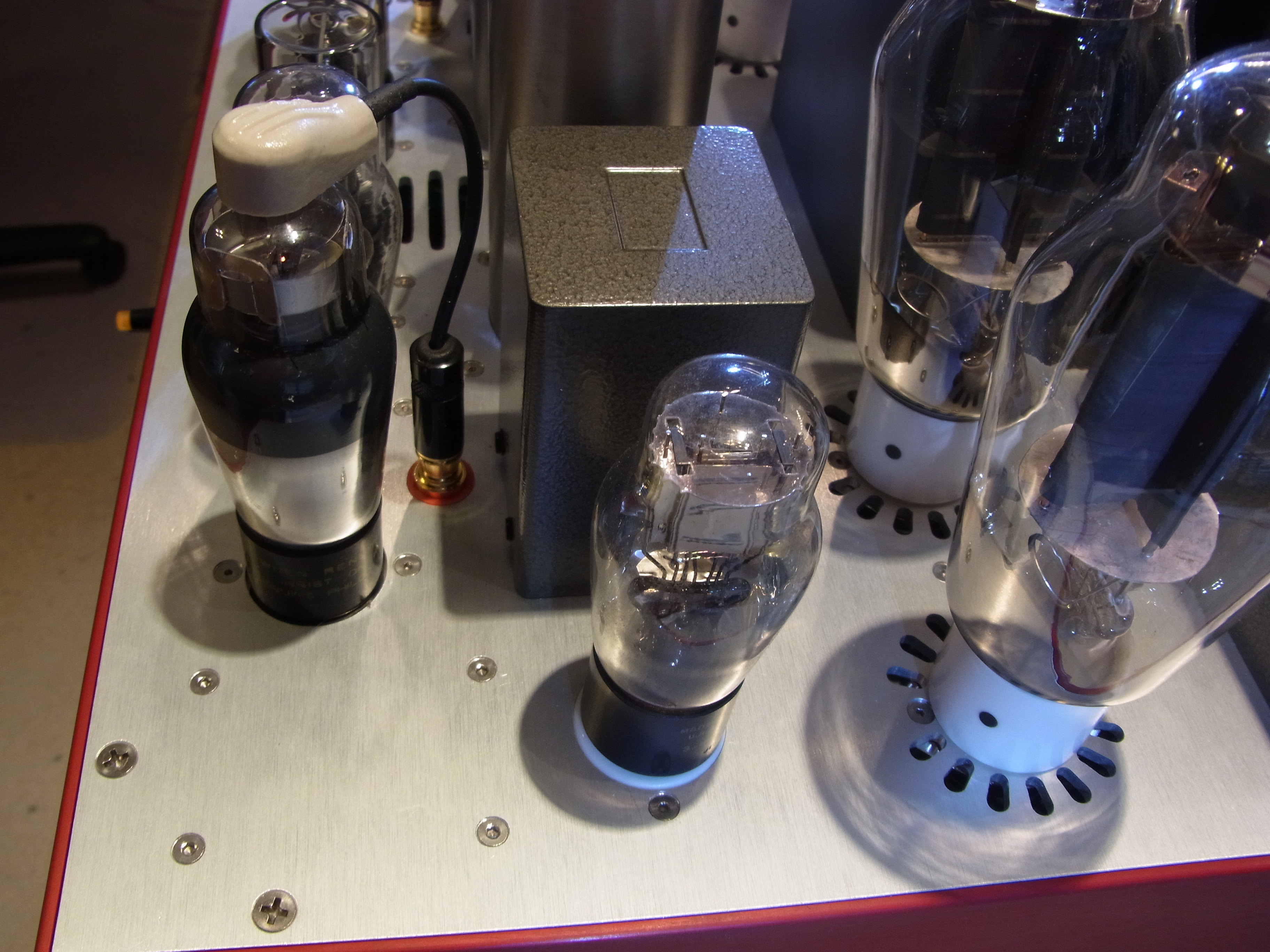
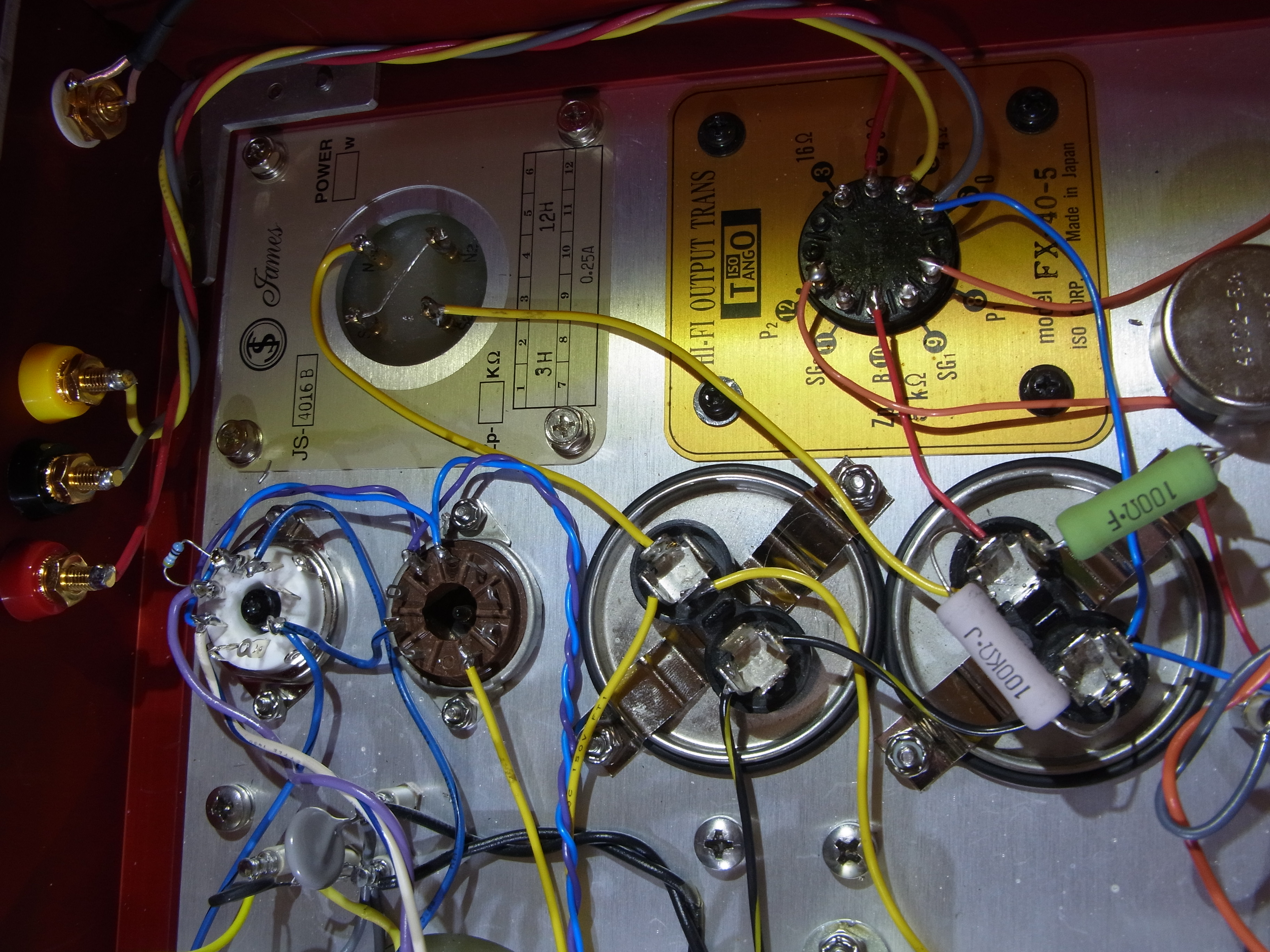
Here are photos of the amp inside & out. Click the photo for a full resolution version...
Measurements
Here are some measurements of the completed amp:
Frequency response at 1W into 8 ohms:
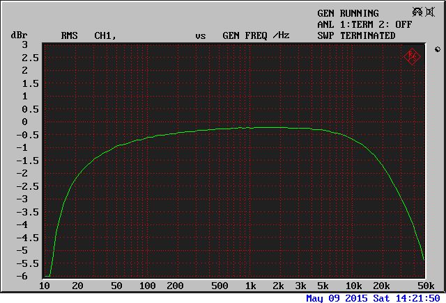
Basically down 2dB at 20Hz and at 20kHz, -3dB at 15Hz and 30kHz. The limitation comes mostly from the magnetics - the plate choke on the first stage, and the interstage transformer, both contribute. Some might argue that -3dB @ 30kHz isn't good enough, but I think it is.
Output power (yellow) and THD (green) vs. input voltage (1kHz):
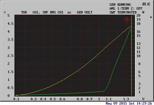
You can see we get about 12W at the beginning of clipping, and close to 19W at 5% THD. This is biased heavily into class A, at about 130mA per pair. You can bias it at higher current, but it doesn't make a big difference. You can also move it down into class AB, which increas4es power output slightly at the expense of higher distortion. Note that with the transformer coupled driver, the 300B does go into A2 operation a little bit.
Here's a zoom showing more detail up to 10 watts:
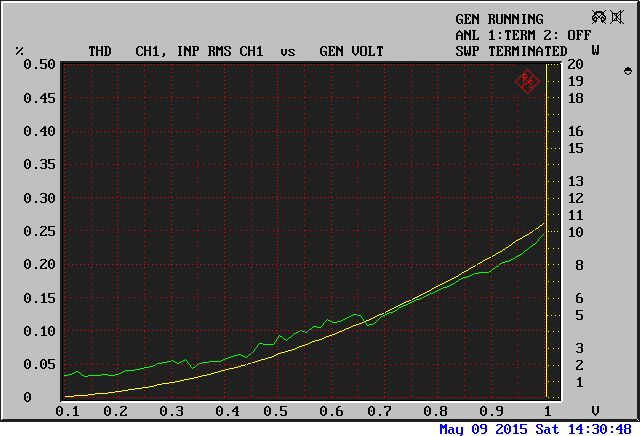
Close to 0.2% THD at 10 watts. Pretty good for zero-feedback 1930's technology. Try that with silicon!
THD vs. frequency (1W into 8 ohms):
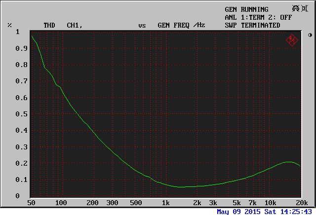
If there is a downside to interstage transformers and plate chokes (other than the expense, which is significant), it is shown here. You can see LF distortion due mostly to the limited inductance of the magnetics. At high frequencies, parasitics (mostly inter- and intra-winding capacitance) comes into play. That said, performance in the midrange, where vocals lie and the ear is most sensitive, is good.
FFT, 1kHz 1W into 8 ohms:
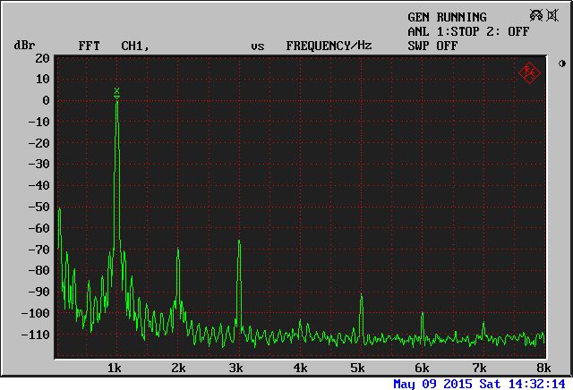
Here you can see the even order distortion cancellation inherent in push-pull stages. The 3rd is slightly above the 2nd. The remaining 2nd is from the input and driver stages as well as output tube mismatch. Still, both are close to -70dB. This is about 0.08% with 400Hz - 30kHz bandpass filters enabled.
FFT, 1kHz 10W into 8 ohms:
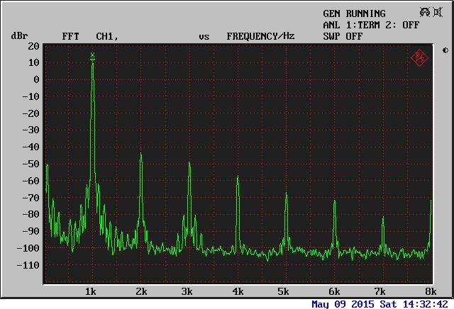
The FFT at 10W is well behaved, with a nice "waterfall" of harmonics. THD here measures about 0.2%.