Two-channel shunt-regulated bias supply
This is a two-output, shunt-regulated bias supply. I designed it for a push-pull 300B amp, but it can be used in any application where you need a regulated, adjustable negative bias supply.
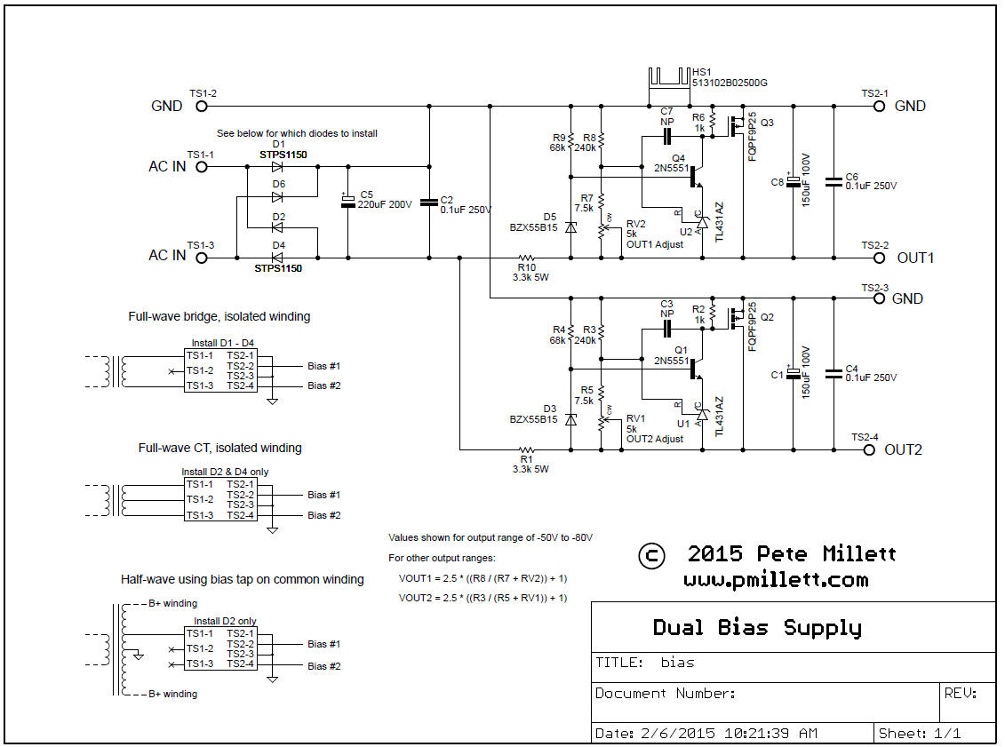
Here is the schematic (or download it as a PDF file):
Note that the component values shown are for my application, which has ~100V RMS AC input and an output range of -50 to -80VDC (for 300B tubes). For other applications you will need to change component values. As shown on the schematic, the output voltage range is set by both fixed resistors and the adjustment pots. You can select the ratio of the pot to the resistor in series with it to set the adjustment range, and then set the upper resistor to get the output voltage you need. In any case keep the upper resistor (R3 and R8) above about 100k, so you do not burn too much current in the feedback divider.
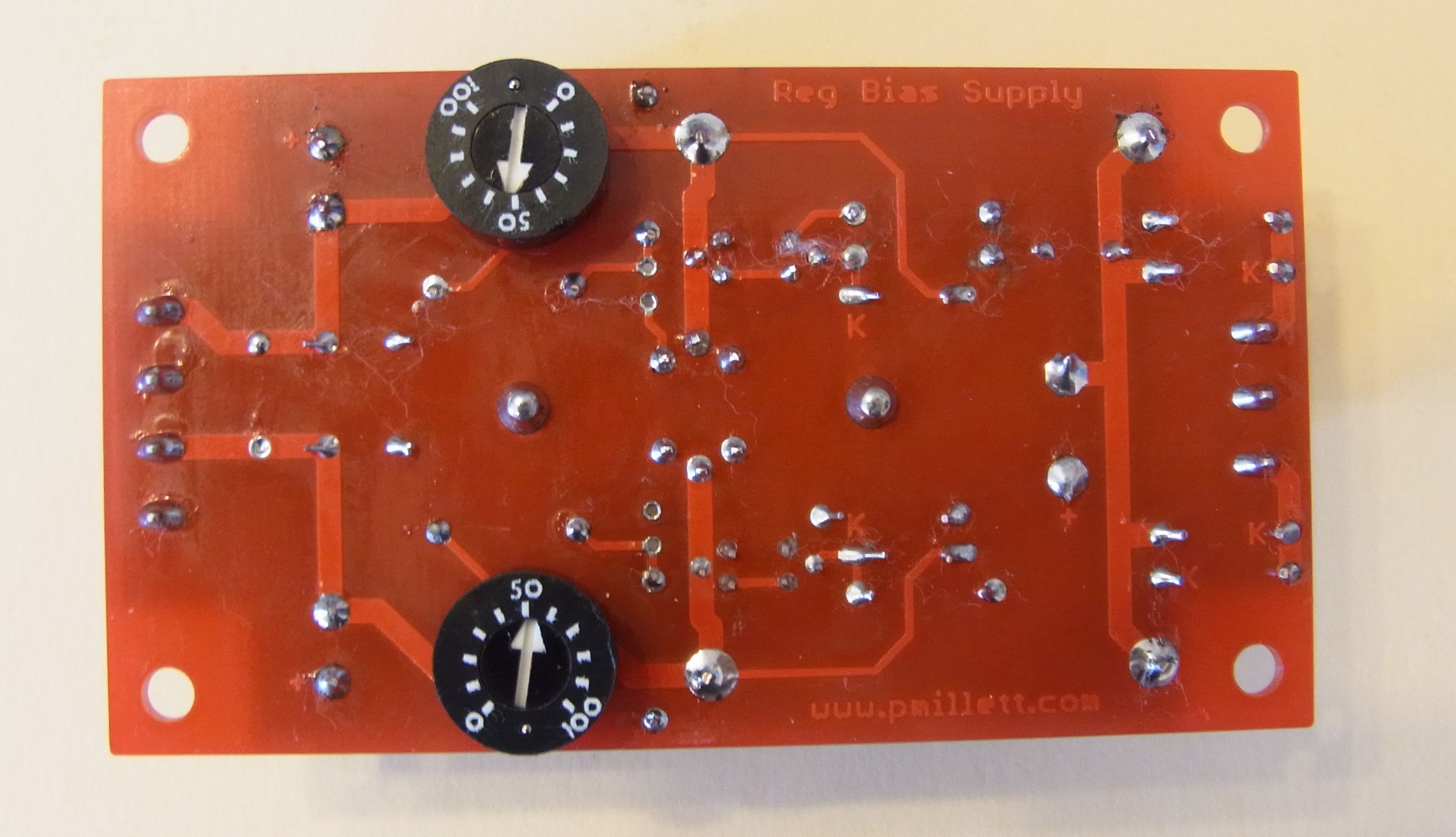
There are several types of adjustment trimpots that will fit the PCB. The PCB has holes on 0.1" x 0.1" centers, which fit either 1/2" round or 3/8" square single-turn trimmers. You can mount them on the front or back of the PCB, depending on how you want to mount the board (I put them on the back so I can access them through a hole in the top of the chassis). I like the BI electronics "PR series", shown in the picture below.
Here is the parts list (BOM) for my application in PDF or XLS format. Again, you will likely have to change some resistor values for your application.
The series resistors (R1 and R10) set the quiescent current through the regulator. You want to keep a minimum of about 10mA flowing through the shunt regulator. So, if you have no output load current (as would be the case for a basic grid bias), pick a resistor so that the rectified DC voltage (using whatever transformer you are using) across C5, minus the desired maximum output voltage, gets you about 10mA. This value is not critical... more current will just cause a little more power dissipation in the FET and resistor. You need to keep under the resistor power rating (5 watt resistors will fit, maybe even some bigger ones), and the heatsink can dissipate around 4 watts (depending on how hot you're willing to let it get). You can use a taller heatsink if needed.
If you have DC output current (for example, you are using the bias supply for a CCS tail), you need to add that current with the 10mA minimum through the shunt. So, the series resistor would need to be smaller.
You need to have enough input voltage so that the regulator has headroom to operate. In other words, the series resistors need to drop some voltage. If the output voltage gets too close to the input voltage, the circuit will go out of regulation, and you'll get a lot of ripple on the output.
You can power the circuit with either its own transformer, using a FW bridge or FW center tap rectifier circuit, or from a bias tap on a power transformer with a grounded center tap using a half-wave rectifier. Refer to the schematic for hookup instructions. I would recommend using Duncanamps PSUD simulator to figure out the transformer and input rectifier circuit.
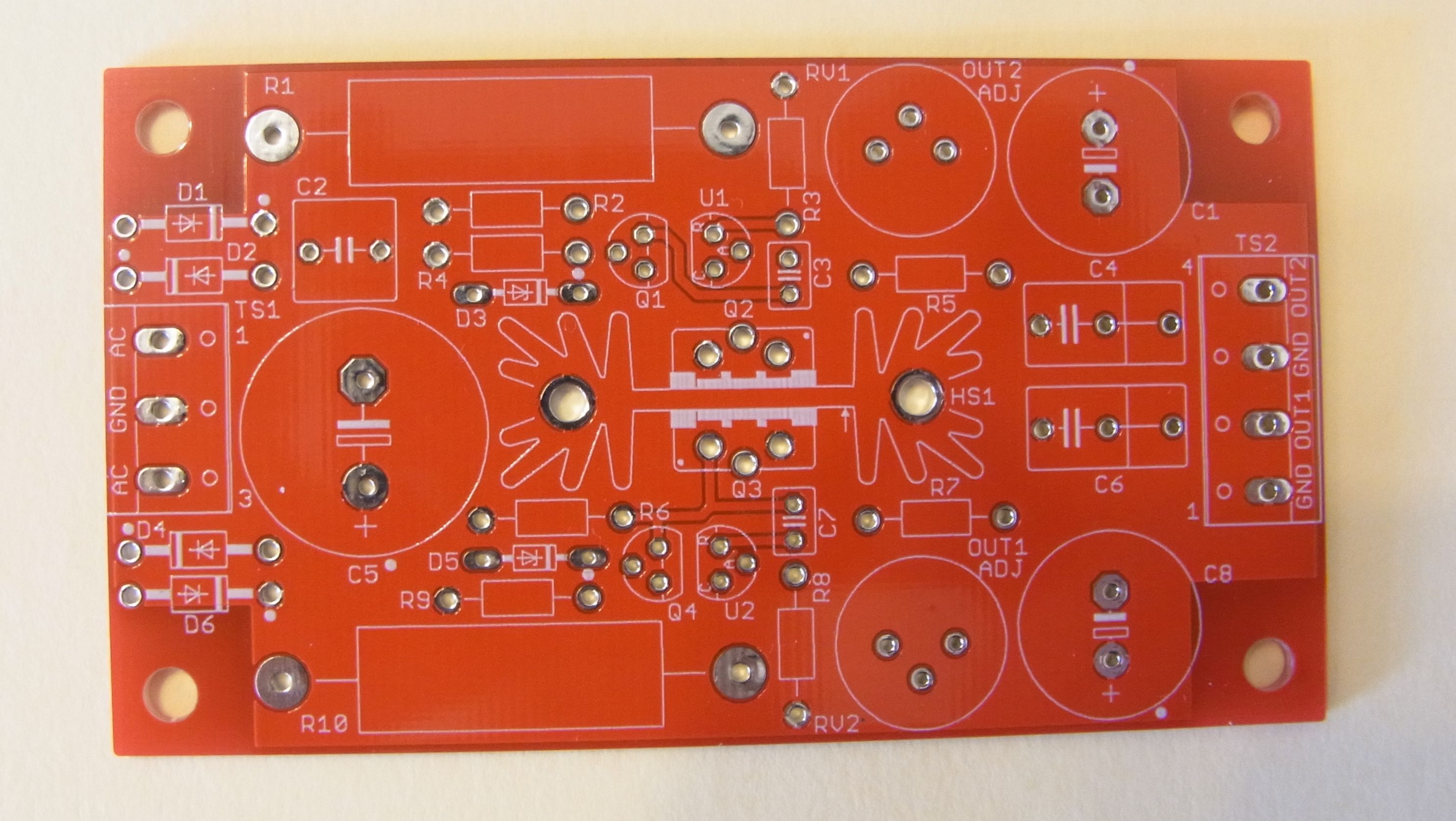
Here is the PCB, available on eBay:
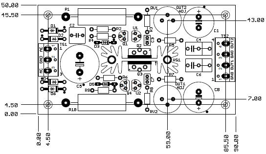
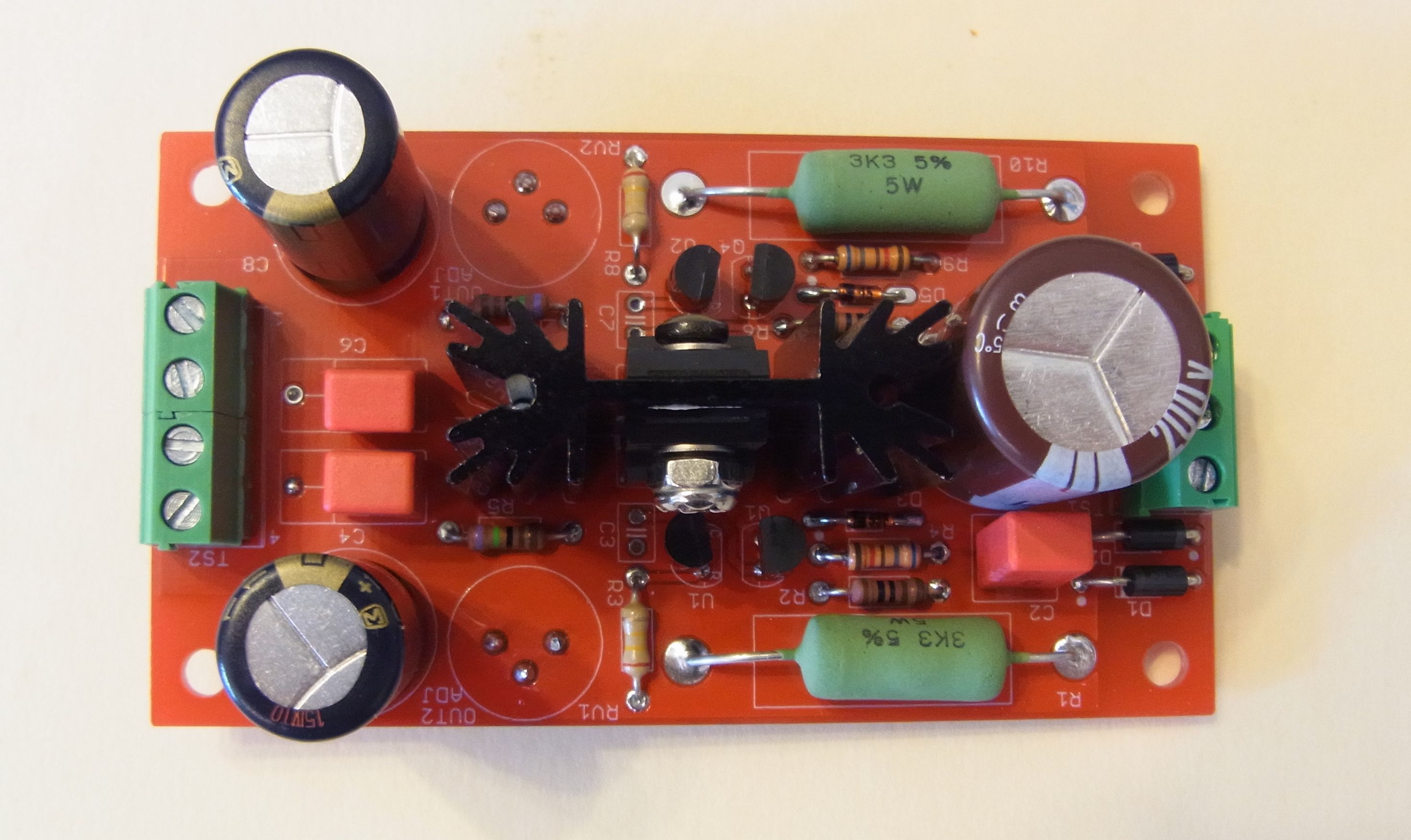
The assembled PCB: