10W B+ Flyback Supply
This is a switching power supply to generate low-current B+ voltage from a low-voltage (5-20V) DC input. It is a non-isolated flyback converter (input ground is the same as output ground). It can generate about 10W of power, depending on input and output voltages.
I designed this to provide high voltage power for a line stage (preamp). I use it in "el escorpion", a line amp built in a cigar box. It's an easy, small, and relatively safe way of getting a B+ supply for a low-power tube project.
Here's the schematic (or download it in PDF):
The supply uses a Linear Technology LT1171 IC, which makes the circuit pretty simple. The LT1171 integrates the controller and the output FET, so all you need to add is the feedback, compensation, input and output components. I chose to make it non-isolated mostly to simplify the design, but I also think that the most common use of this is to generate B+ from a DC supply (like a car battery, or an external AC supply) that will also power the heaters, so isolation is not needed.
There are LC input filters on the input (to reduce noise coupled backwards) and the output (to reduce high frequency noise at the output). Switching frequency is 100kHz. The output transformer is an off-the-shelf unit from Coilcraft (Y-8848A) that is designed to generate 12V at 10W from an AC input of 85-265VAC. It is used here in "reverse", with the high voltage primary being used as the secondary.
As I designed it, the output voltage can be set anywhere between about 90V and 325V. There is a trimpot to set the voltage and two resistors that are selected for the desired voltage range. I have not tried it but it should work up to about 400V. The maximum output current varies, depending on input and output voltage, but in general is constrained to about 10 watts. If you switch to an LT1170 IC which has a higher current limit, you may be able to squeeze out more power, but you may also start saturating the output transformer.
As is always the case, the compensation network is a compromise. I designed it by using LTspice, then tweaked it using actual measurements. I wanted the loop response to cross at a pretty low frequency - I want audio frequency currents flowing through the output caps, not being chased by the feedback loop. But you do want the loop to respond to 120Hz ripple on the input supply, so it doesn't get through to the output. To verify the supply's response, I drive a signal back into the output, and sweep the frequency, while observing the output voltage. With the components shown the loop was benign throughout the audio band.
If you'd like to play with it in simulation, here is an LTspice .ASC file.
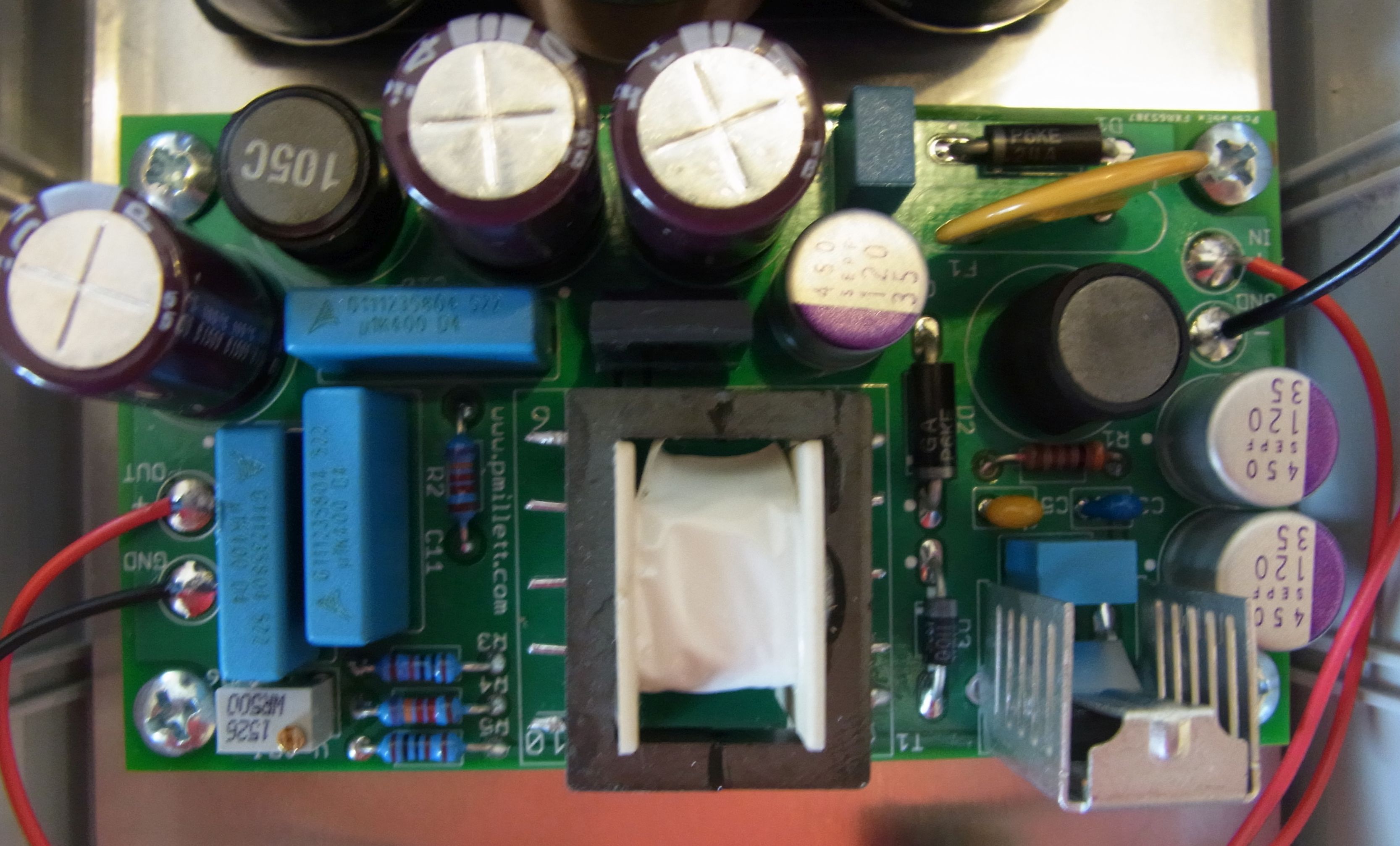
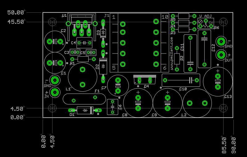
The PCB is a simple through-hole board, 50mm x 90mm in size:
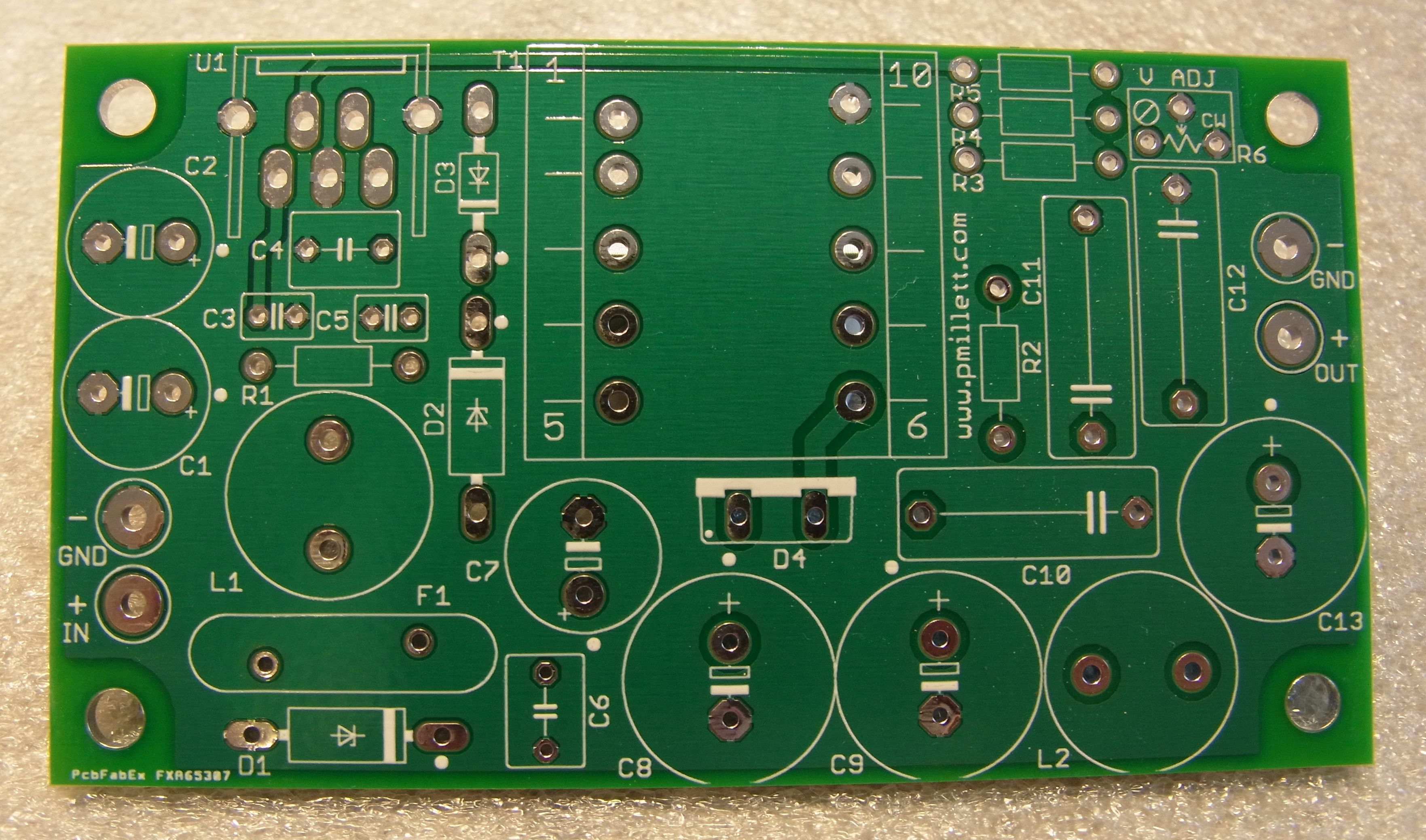
It's very easy to build. All parts except the transformer can be bought from Digi-Key - as mentioned above, the transformer can be purchased directly from Coilcraft (you can buy 1 piece through their web site).
Here is the parts list (BOM), in .XLS or .PDF format.
As usual, I will make these boards available from my eBay store.