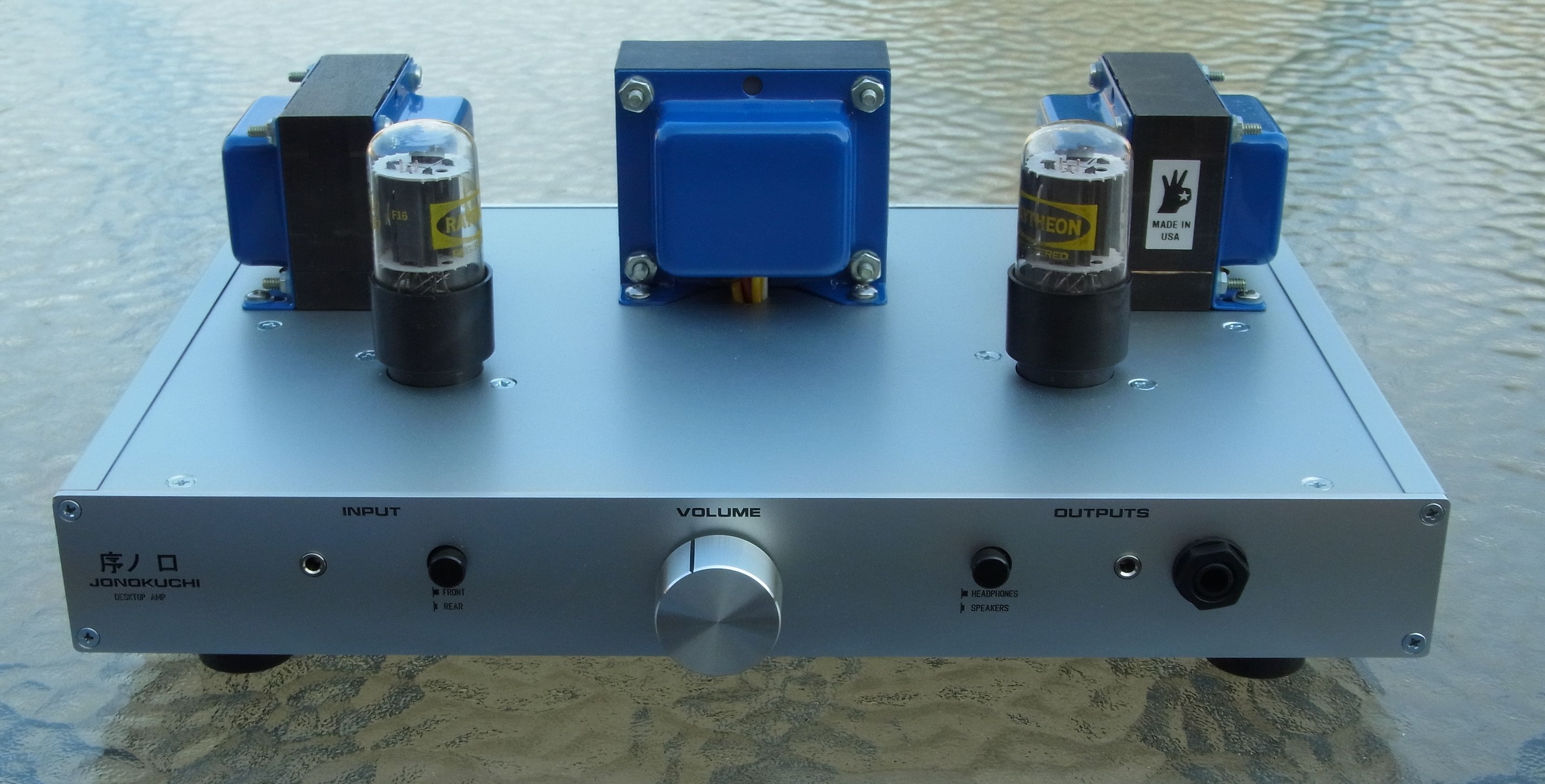
"Jonokuchi" - Desktop headphone / speaker amp using 13EM7 tubes
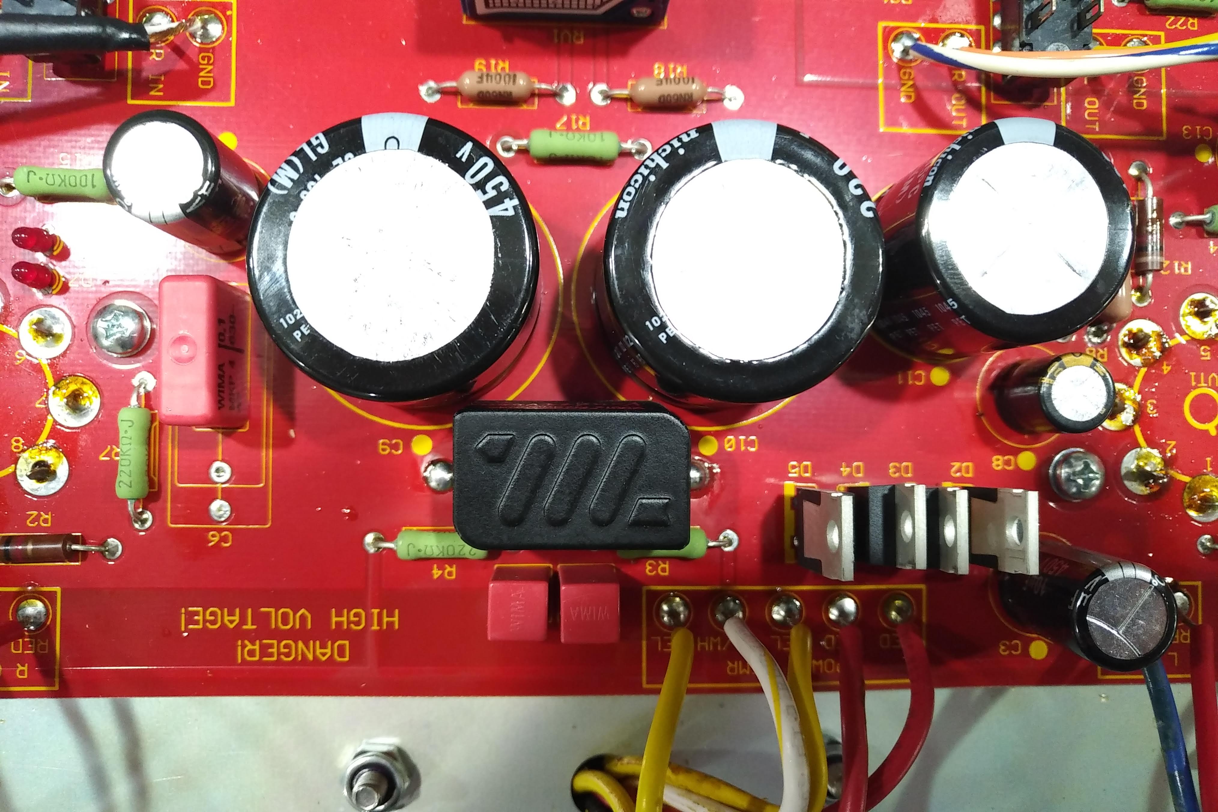
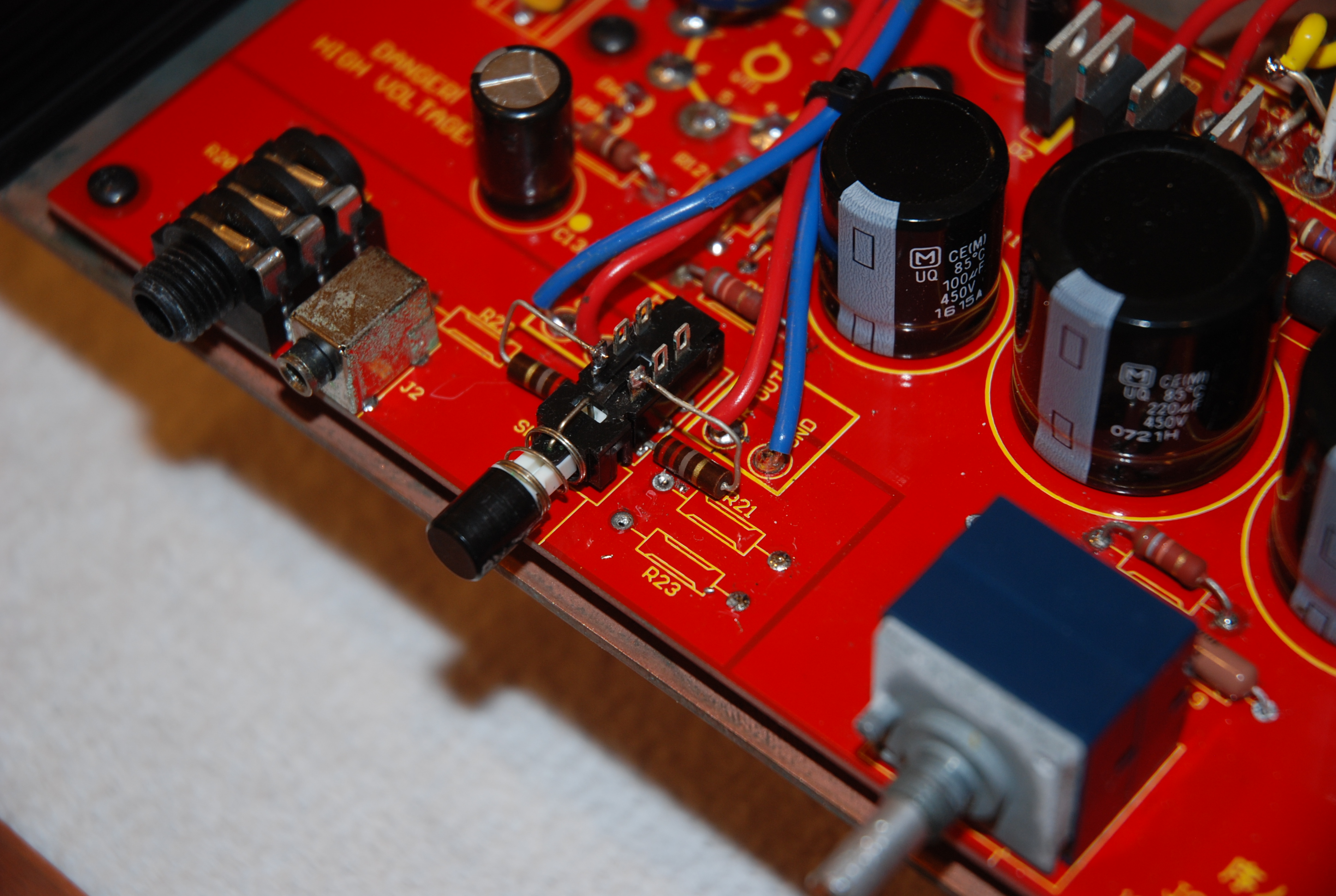
UPDATED 12/23/18 - The Tentabls MEC-100 works great in place of the series resistor in the power supply:
Note the direction. The leads are a little short but you can make it work. The MEC reduces the power supply ripple significantly, and might reduce the hum level (I don't really hear any myself either way).
(Photos are hyperlinked to full-size images - click on them for detailed view)
Sometimes, conventional is OK.
I've had a lot of people ask me for a tube headphone amplifier design that can also drive small, efficient speakers (like computer speakers). I've gone through a lot of different topologies, including odd things like class A2 triodes and even a hybrid with a class-D speaker stage... but finally settled on a perfectly normal single-ended amp using 13EM7 tubes.
The 13EM7 is a 13V heater version of the 6EM7, which is a dissimilar dual triode that was designed for vertical oscillator and amplifier service in TVs. 13EM7 tubes are readily available (a poll of a couple of tube vendors showed thousands in stock) and are inexpensive.
The amp design was optimized for headphone use, but still makes a fine amp to drive small speakers to reasonable levels.
I wanted this amp to be as easy to build as possible, so a beginner could make it. The name - "Jonokuchi" - refers to the lowest rank of sumo wrestlers in Japan. It can be roughly translated as "just beginning" in English.
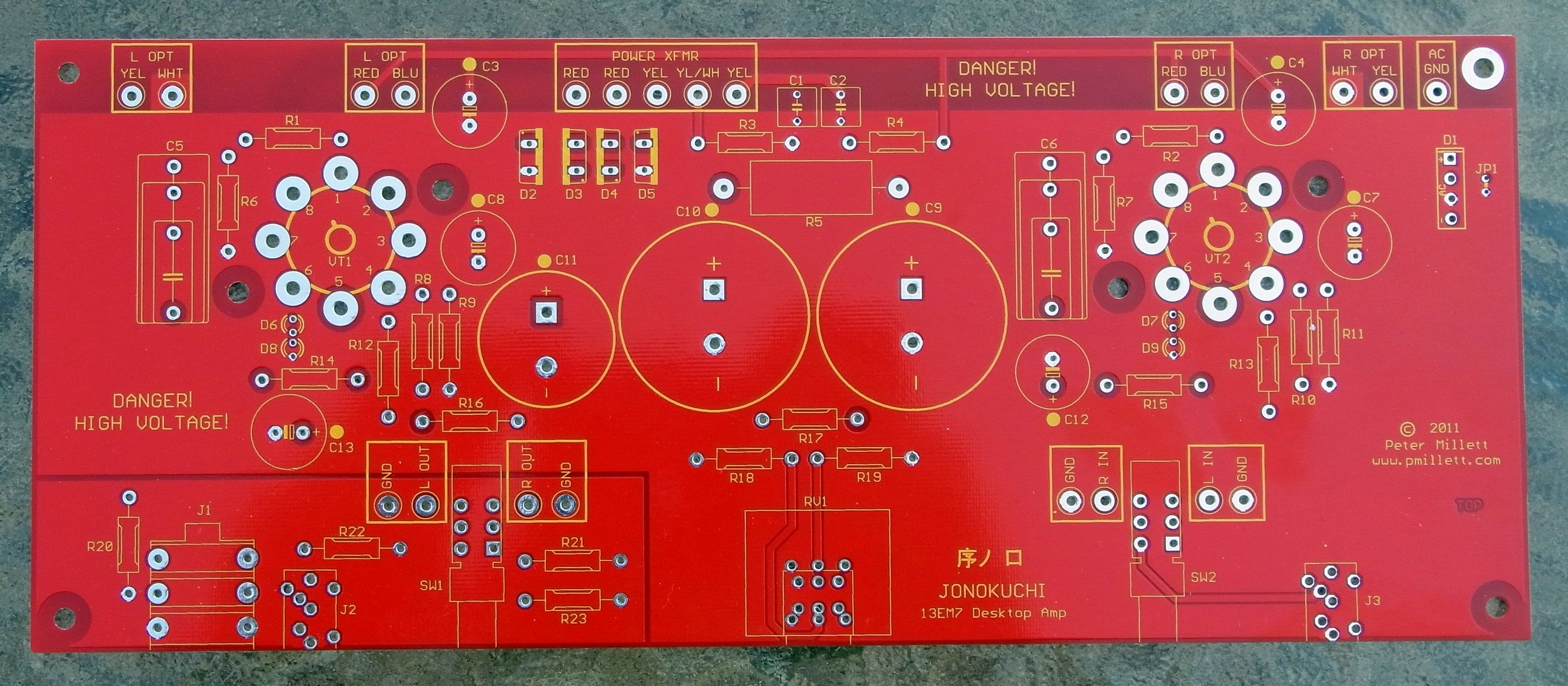
To make it easy to assemble, I designed a PCB that contains all of the components except the transformers and input, output, and power jacks (which are mounted on the back panel). The PCB is available for sale on eBay.
For more experienced builders, this is a pretty easy amp to build using conventional point-to-point wiring.
I also wanted the amp to be inexpensive. The total cost using the PCB is about $200, plus enclosure. The enclosure options range from an inexpensive aluminum chassis up to the full custom enclosure shown above, made by Front Panel Express.
The design
Jonokuchi is a conventional single-ended, 2-stage amp.
Cathode bias on the first stage uses LEDs. The second stage uses cathode bias resistors that are partially bypassed by a cap, giving the combination of gain, distortion, and output impedance that I wanted. If you want, you can play around with the ratio of the two resistors.
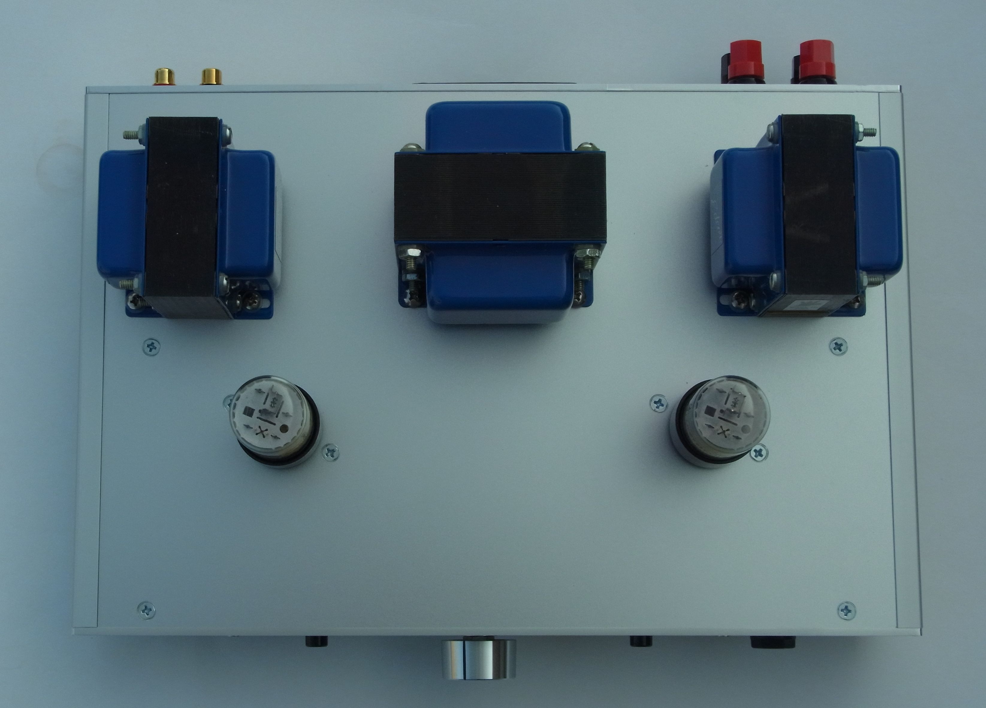
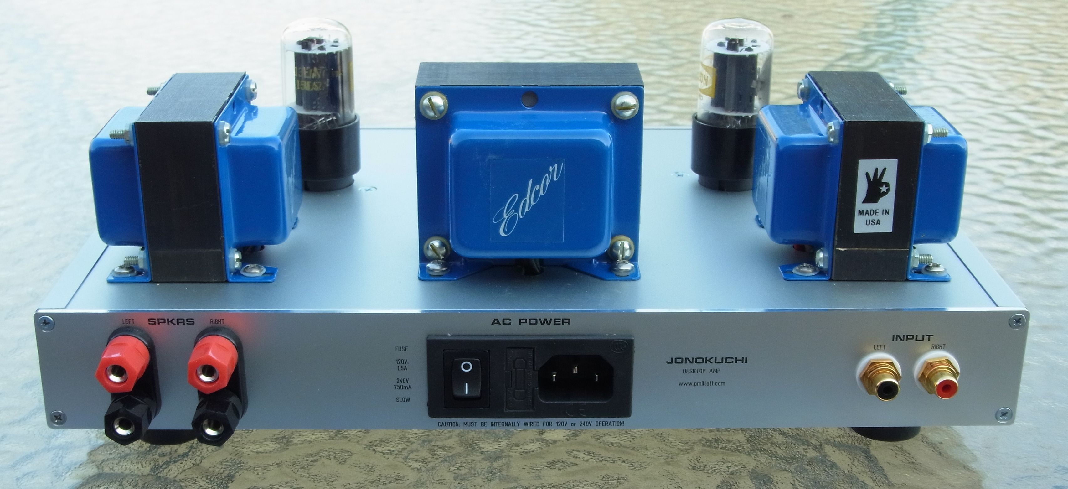
The OPT is an off-the-shelf 8k:8 ohm SE transformer from Edcor (GXSE10-8-8k). 8k is a higher load than most people use for a 13EM7 (6EM7) amplifier... I did this to get the distortion and Zout low. This is part of optimizing the amp for headphones and not speakers; if you needed more gain and more output power, you could use a lower impedance transformer, like 5k or even 3.5k.
Two inputs are provided. One uses a 1/8" stereo jack mounted on the front panel (to connect an iPod or other device); RCA jacks are mounted on the rear panel. A switch on the PCB selects between inputs. A board-mounted Alps (or optional cheaper Alpha pot) controls the level.
I put both 1/4" and 1/8" headphone jacks on the front panel. Binding posts for speaker connections are mounted on the rear panel. Again, selection of speakers or headphone is made by a board-mounted switch on the front.
So, how can the same setup drive both speakers and headphones? It really is not all that difficult, at least at the low power level that this amp operates at. When switching to headphones, 10 ohm resistors are used as a load across the output. This keeps the OPT loaded with a reasonable load at all times. Headphone impedances of 16 ohms and higher work just fine.
The gain of the amp is low for a speaker amp (about 10dB) - again, optimized for headphones. The result is that with speakers, the maximum output is limited when driven from a standard 1 or 2V RMS line output. Since the amp is intended to run with small near-field speakers (think computer speakers), I find that the gain is high enough.
The power supply is conventional, using a custom power transformer from Edcor (XPWR168-120/240) and solid-state rectification using Silicon Carbide Schottky rectifiers. To save money and space, I used a CRC filter with no choke. B+ is 340V, higher than most 6EM7 amps, to get decent output into the 8k load. Relatively large filter caps reduce the ripple so it is not a factor. The 13EM7 heaters are supplied with AC.
Construction
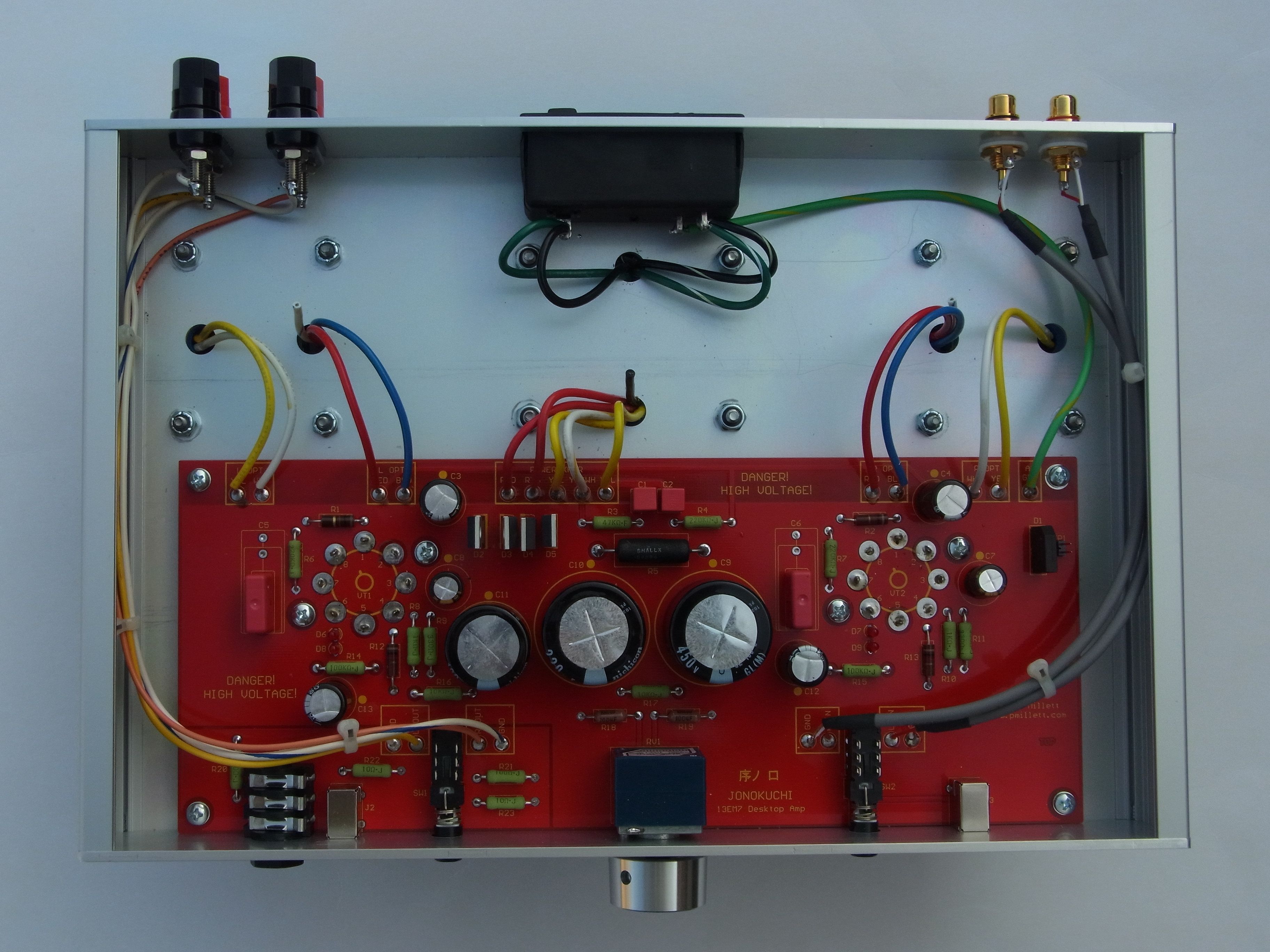
There are two basic options on building Jonokuchi: You can build it using point-to-point wiring techniques, working off of the schematic above. Or, you can buy the PCB and build it the way I did in the photos. Using a PCB is certainly much faster and easier, especially if you are not an experienced builder. P2P wiring will let you customize things a little more.
Construction using the PCB is as simple as inserting the parts into the PCB and soldering them. You can follow the parts list (below) and the photos on this page for reference. I might even get around to writing a step-by-step set of instructions. The PCB is mounted to the enclosure, as are the transformers and jacks on the rear panel.
Here is a bill of materials (parts list) of the amp... in .XLS or .PDF format. The BOM has suppliers (multiple suppliers, in fact) of the parts I used. Of course you can substitute other parts, in most cases. Or you can follow the list exactly.
The cost of construction for the amp not including the enclosure is around $200. The enclosure can cost anywhere between almost nothing and $275 or more, depending on how much work you want to do and what you want it to look like. See the "enclosure" section below.
Performance
Here are some measured specs and performance graphs. I found that the performance does vary significantly tube-to-tube... 13EM7's are cheap, so it's practical to buy 5 or 6 of them and select the ones you like the best, either via measurement or by ear.
| Headphone mode | Speaker mode | |
|
Gain |
11 dB (150 ohm load) 10dB (32 ohm load) |
10dB |
|
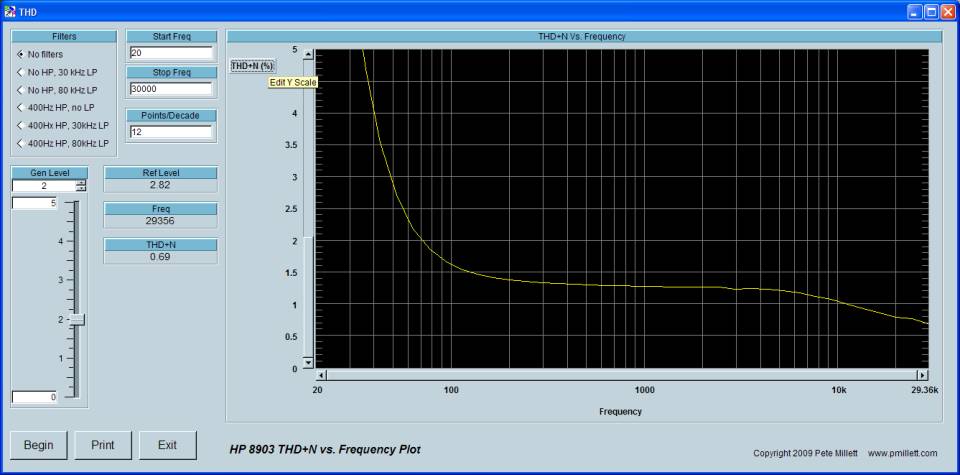
THD + N (at 1kHz) |
0.28% (1V into 150 ohm load) 0.5% (1V into 32 ohm load) |
1.3% (1 watt into 8 ohm load) |
|
Max output @ 5% THD |
4.6V (150 ohm load) 4.0V (32 ohm load) |
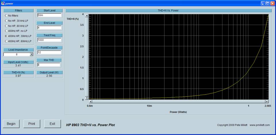
4.5V / 2.5 watts into 8 ohms |
|
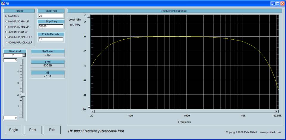
Frequency response (-3dB) |
22Hz - 28kHz (1V into 150 ohm load) 22Hz - 26kHz (1V into 32 ohm load) |
24Hz - 26kHz (1 watt into 8 ohm load) |
|
Noise (unweighted) |
700 uV / 140uV with 400Hz high pass filter |
700 uV / 250uV with 400Hz high pass filter |
Headphone mode graphs
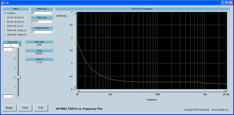
All taken at 1V out, 1kHz unless otherwise specified. 150 ohm load (32 ohms look almost identical)
Frequency response:

THD + N vs. Frequency:
THD + N vs. output voltage (1kHz):
FFT (1kHz 1V out):
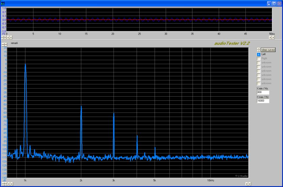
Square wave response (5kHz, ~4V P-P):
Speaker mode
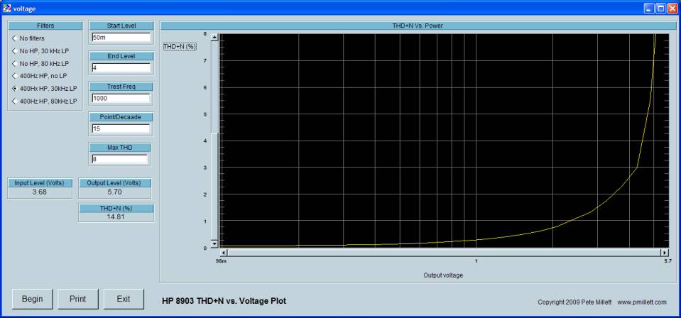
Taken at 1W out, 8 ohm load unless specified.
Frequency response:
THD + N vs. frequency:
THD + N vs. output power:
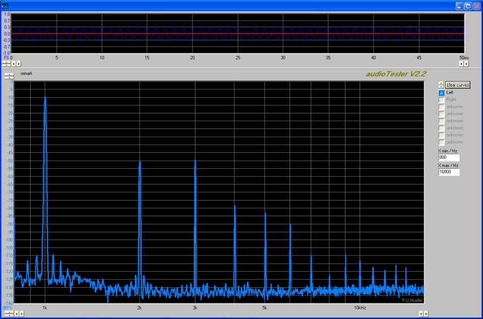
FFT:
Square wave response (5kHz, ~8V P-P):
The enclosure
You have a number of choices on how to enclose the Jonokuchi amp.
An affordable option is to use a standard off-the-shelf aluminum chassis. You have to drill or punch all the necessary holes in the chassis, then finish (paint) it (or not) yourself. Though I didn't build it this way, I did some CAD work for it, using a 8" x 12" chassis like the Hammond 1444-22. Here is a ZIP file that has PDF plots (1x scale, to be printed on 11x17 paper) as well as an AutoCAD DXF file using this chassis. You can use the paper plots as a drilling guide for the chassis. If you have access to some mechanical CAD programs you can use the DXF file as a starting point.
I went all-out and designed an enclosure using Front Panel Express panels and side extrusions... this is shown in the photos. The upside of this enclosure is that it looks great, and you don't have to do any metal fabrication to get it. The down side is cost - this enclosure will cost as much or more than the electronics.
You can just call up Front Panel Express and tell them you want to order the "stock" Jonokuchi chassis - they have all the data to reproduce the one I made. If you give them this discount code - AEUNB2XA - you will get 20% off as well!
Alternatively, if you want to make some tweaks to the enclosure, here's a ZIP file that contains all of the .FPE files for the parts (front, rear, top, and bottom). You need to download the Front Panel Designer program from FPE to open these. You can then modify or customize the panels if you wish.
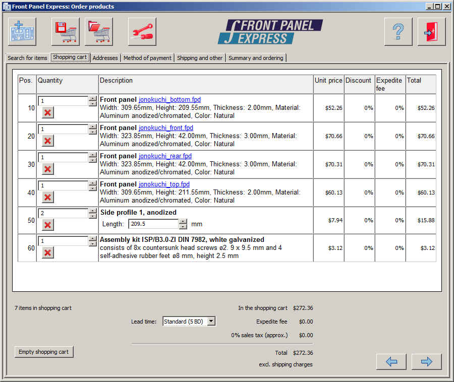
When you order the panels, you also have to order two side extrusions ("side profile 1", 209.5mm long) and an assembly kit (contains screws to assemble). Here is a screen shot of my shopping cart with all the parts:
In either case, the PCB is mounted to the enclosure using #6-32 x 1/4" standoffs. I used female-female standoffs.
I used big rubber feet mounted to the bottom panel of the chassis with screws, instead of the small stick-on feet that FPE supplies.
Update 5/28/12 - Reducing Headphone Hum
Several users have reported some hum in headphones, especially low-impedance headphones. I believe the source of the hum is mostly magnetic coupling from the power transformers into the output transformers.
One solution to this is simply to use a bigger chassis, and provide more space between the transformers.
Another solution that has worked for at least one builder is to insert series resistance between the amp output and the headphone jack. He came up with a clever way to do this:
To implement this mod, the two front pins of the headphone/speaker switch are cut off. (The switch has to be removed to do this, unless you do it as you're building it). Into the hole that was filled with the now cut off pin, one end of a resistor (220 ohms was used here) is soldered. Then, the switch is re-installed and soldered in. The free end of the resistor is then soldered to the solder eye on the top of the switch. This is shown pretty clearly in the photo above.
The load resistors R22 and R23 also have to be removed, unless you want a lot of attenuation as well. If you want some attenuation, you can place these resistors. As an example, if they are the same value as the series resistors, you'll get 6dB of attenuation.