50 watt Nutube / class-D hybrid amp
Update 12/13/18 - Fixed incorrect PCB dimensions!
Here is a hybrid amp using the Nutube low power triode in the front end of a 50 watt class-D amp.
The amp design
The amp uses a Nutube gain stage in front of the class-D chip, an MP7770 from Monolithic Power Systems (MPS).
Here's the schematic (click for full size, or download a PDF file):
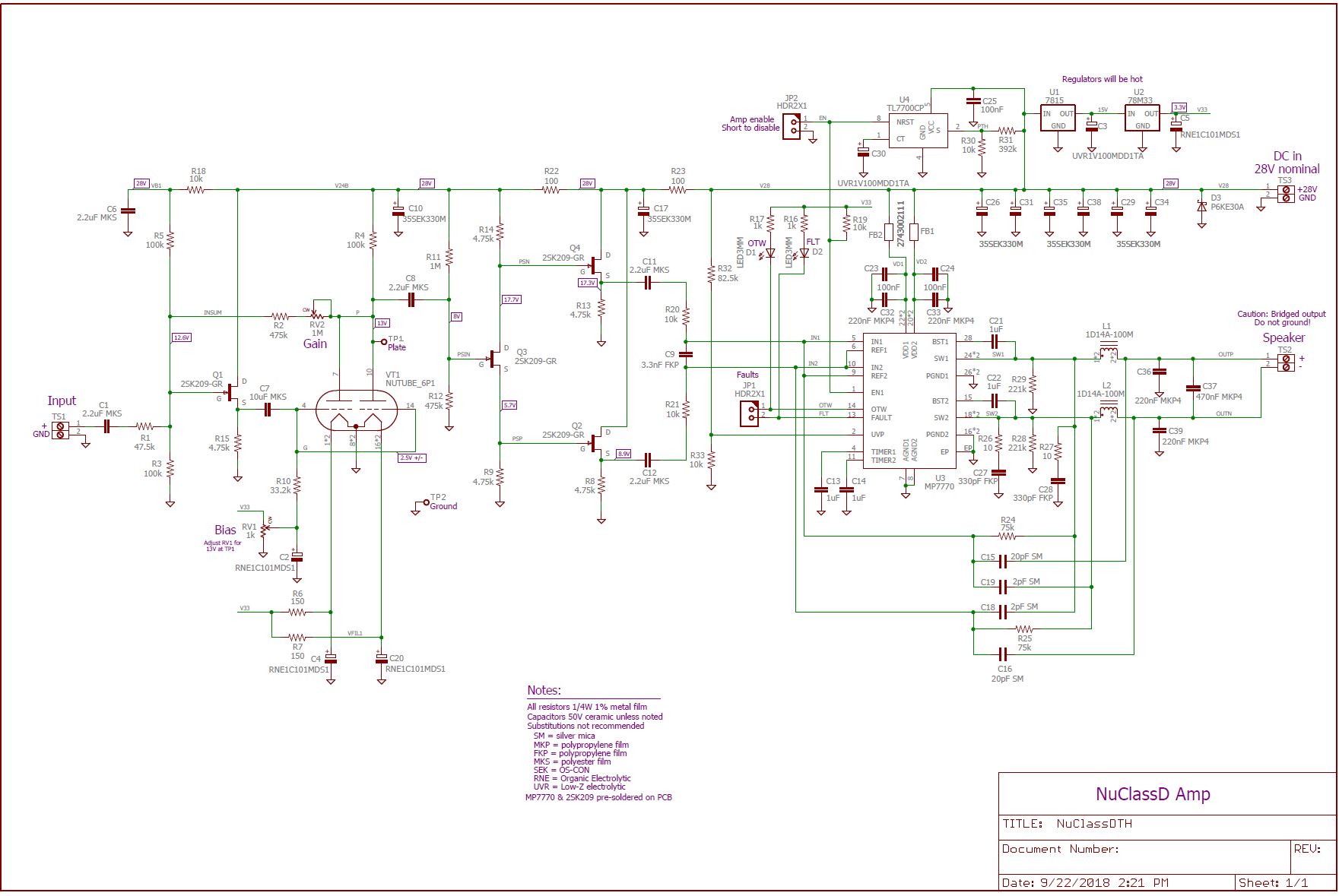
You will see a JFET buffer in front of the Nutube - needed because the Nutube is being run in class-A2, so it eats some grid current. Following that is a JFET phase splitter and JFET followers, to drive the fairly low input impedance of the class-D circuit. There is a little NFB around the Nutube plate-to-grid, adjustable with a trim pot. I put the pot there mostly to be able to match up the gain between channels.
The bias point is set by a trimpot. Measure the voltage on the plate of the Nutube (TP1) to ground (TP2). You can try different settings to get different distortion. Minimum distortion is usually around mid-supply (14V).
The MP7770 is a fairly obscure part. It's a self-oscillating class-D amp, not unlike the highly regarded amps from Hypex which have been quite popular with audiophiles.
The MP7770 is technically capable of 90 watts into a 4 ohm load, but is being run a bit more conservatively here, and can deliver 50 watts into 4 or 8 ohms, using a 28V power supply. It is operated in bridge-tied-load (BTL) mode with differential inputs (hence the phase splitter in front).
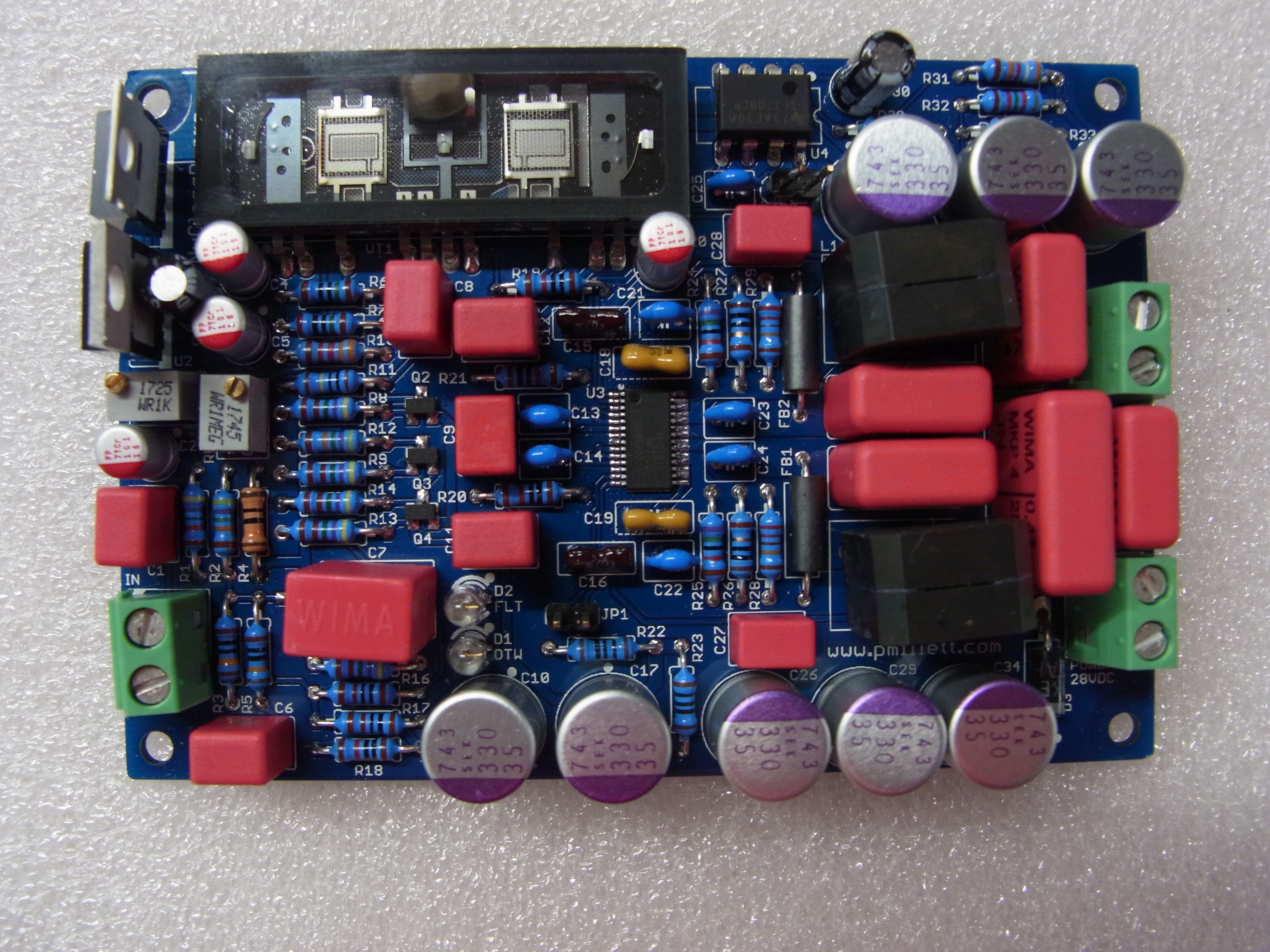
Since pretty much all class-D amps are only available in surface mount packages, and it is critical that they be well soldered (the exposed pad on the underside of these devices is needed to heatsink the part), I decided to make a PCB available with the surface mount parts already soldered on. I also included the JFETs, since through-hole JFETs are a bit difficult and/or expensive (sorry, Linear Systems).
At the upper right of the schematic you'll see linear regs cascaded to spread out the power that drive the filament of the Nutube. There is also a power-up reset circuit that's used to gate off the MP7770 during power-up and power-down, so there are no clicks or pops.
Here's what the (almost) bare PCB looks like:
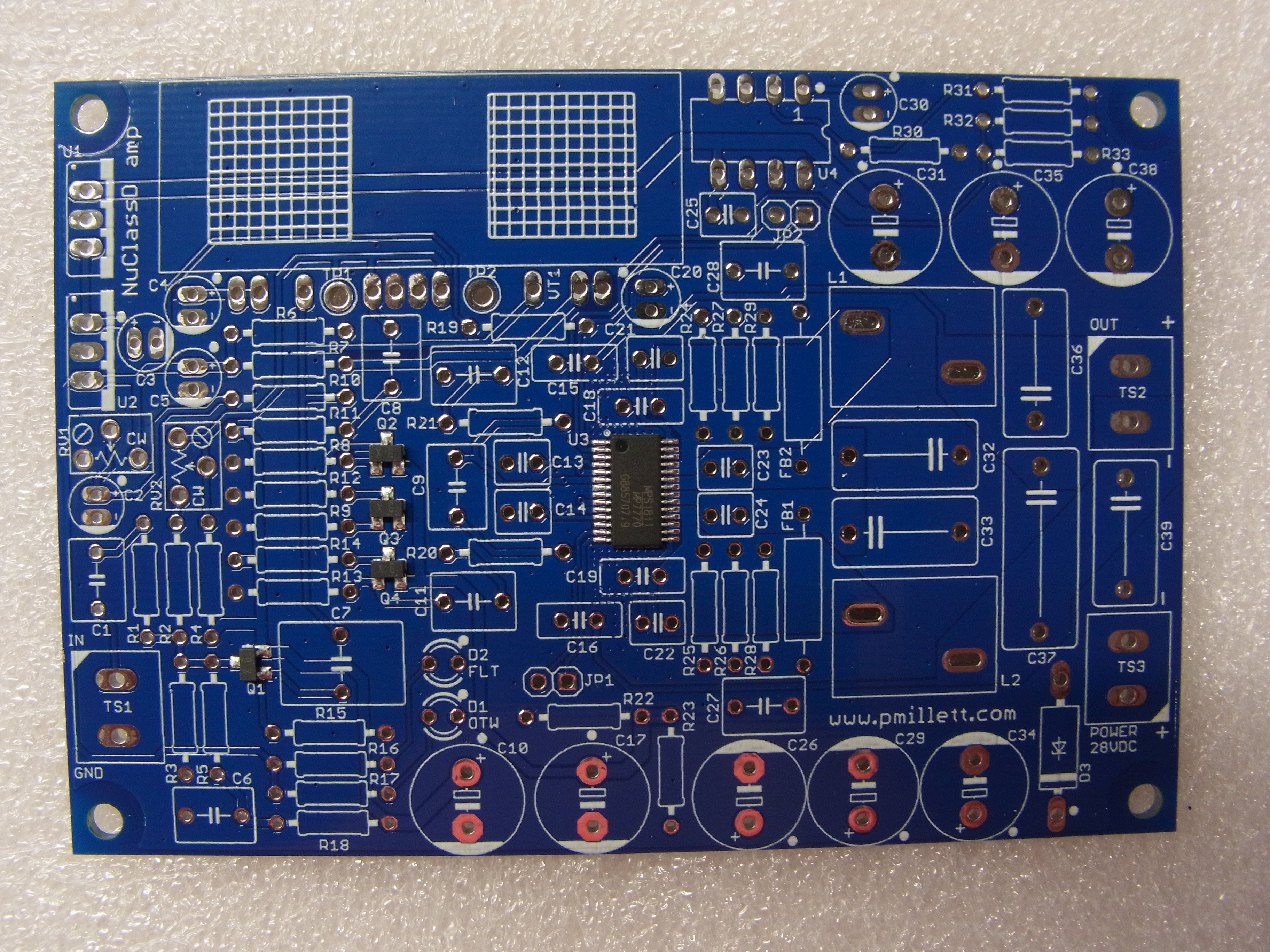
As usual, I'll sell these (with a Nutube) in my eBay store.
The rest of the parts can be had from the usual sources like Mouser and Digi-Key. Here is the parts list (BOM), in .XLS or .PDF form. Do note that the performance of the amp depends on good quality output filter components, so I would suggest you use the same ones I did.
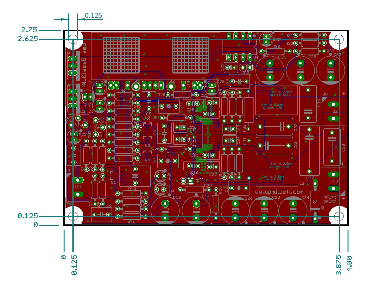
The PCB is small - 2.75" x 4". Here's the measurements (click for full size, or download a PDF):
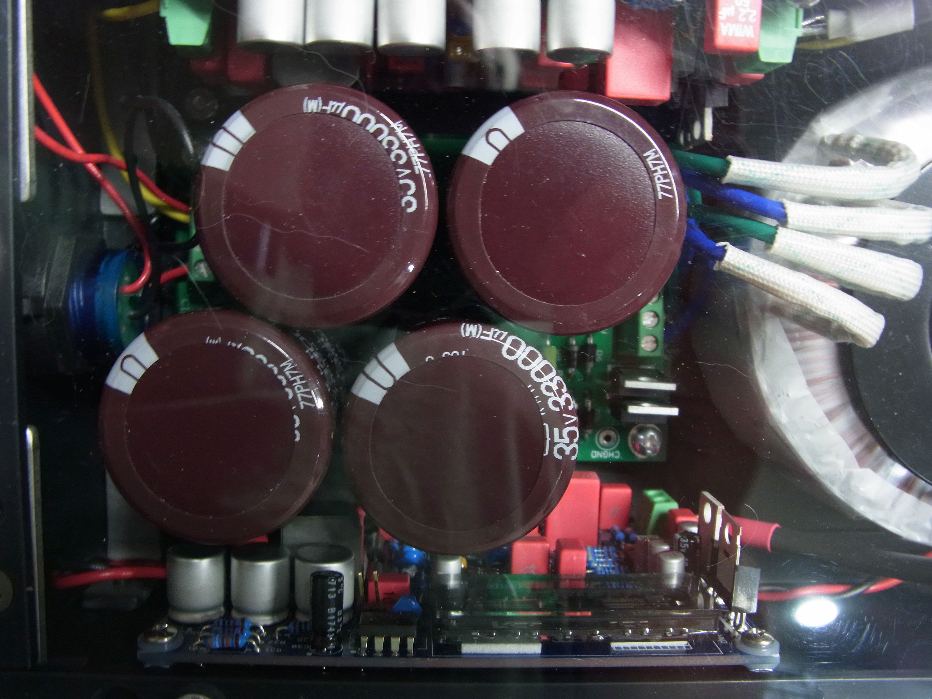
The power supply
To power this, you need a 28V DC power source. I designed a simple brute force linear supply to go with this, using a 100VA toroidal transformer that can provide power for a stereo amp.
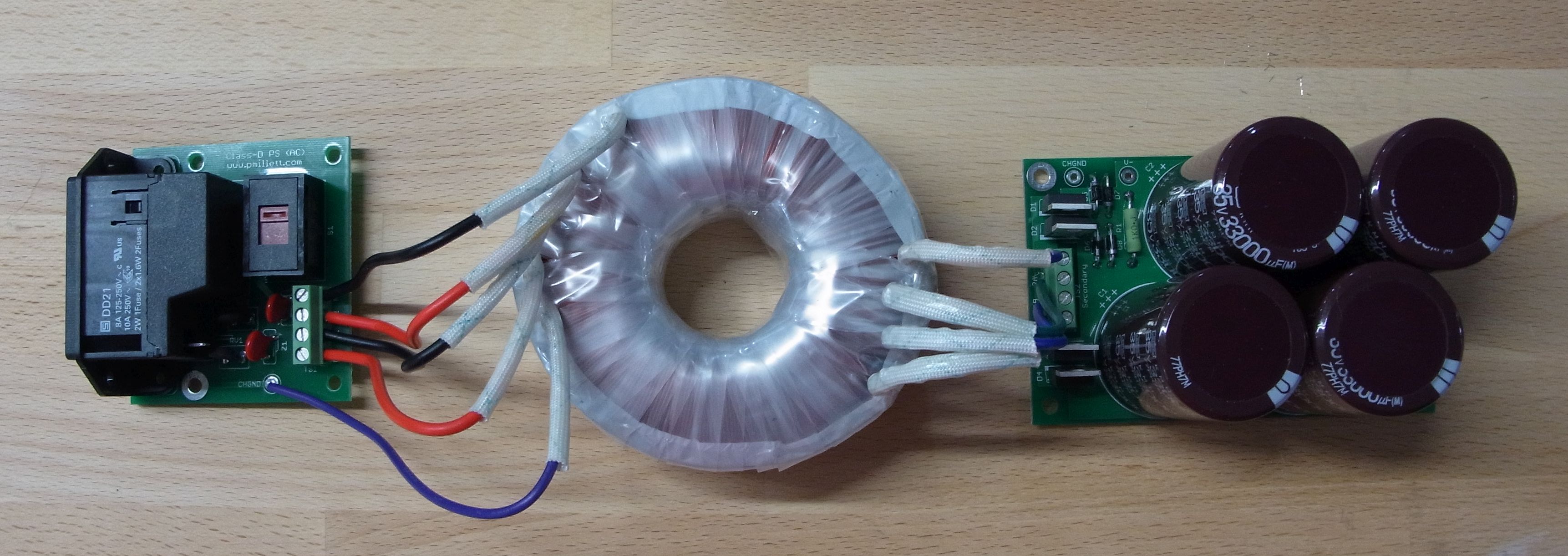
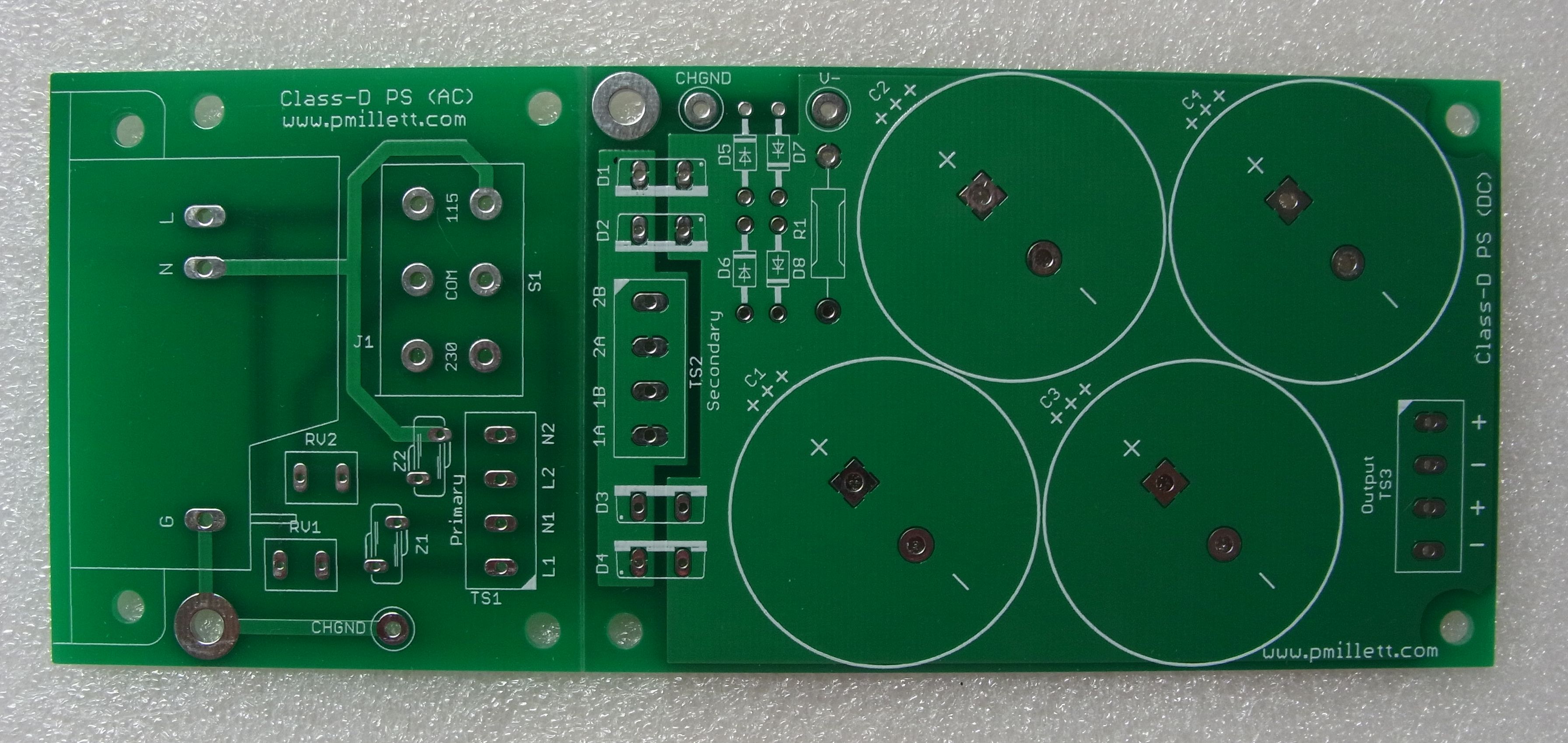
The PCB comes as one board that has a v-score groove. You can leave it together, or snap it into two pieces and put the transformer between them as I did.
Simple schematic (click for full size, or download a PDF):
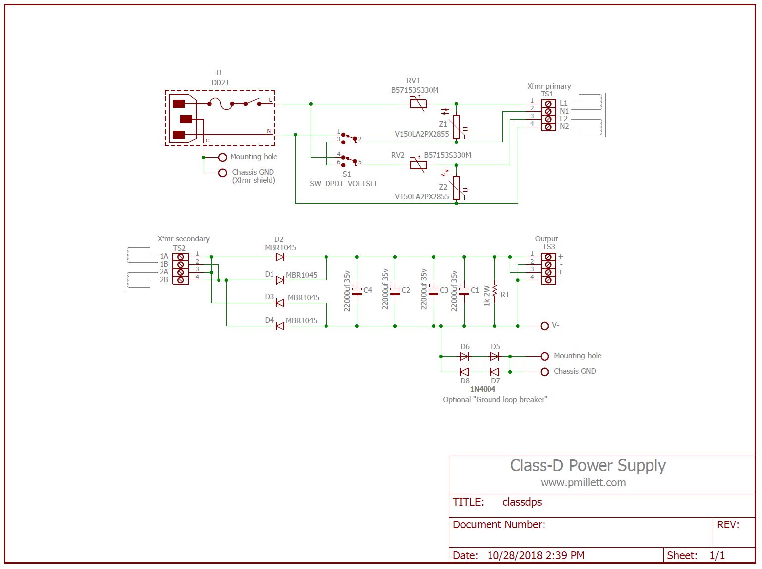
A couple of notes on power:
You want to keep the voltage as close to 28V as possible. The Antek 22V 100VA toroid is perfect for this amp. You will blow up the class D chip and maybe other stuff if the voltage gets over about 35V, so be careful.
I tried using some switching power supplies as well. You have to worry about a couple of things: Switching power supplies don't have much output capacitance, so the turn-off time (fall time) is very fast. It is very difficult to not generate a pop when the power supply drops so fast. One of the beauties of a brute force linear is that the voltage falls very slowly when you kill the power, so the circuit can sense it and perform an orderly shut down so there is no noise.
This PCB will also be available in my eBay store.
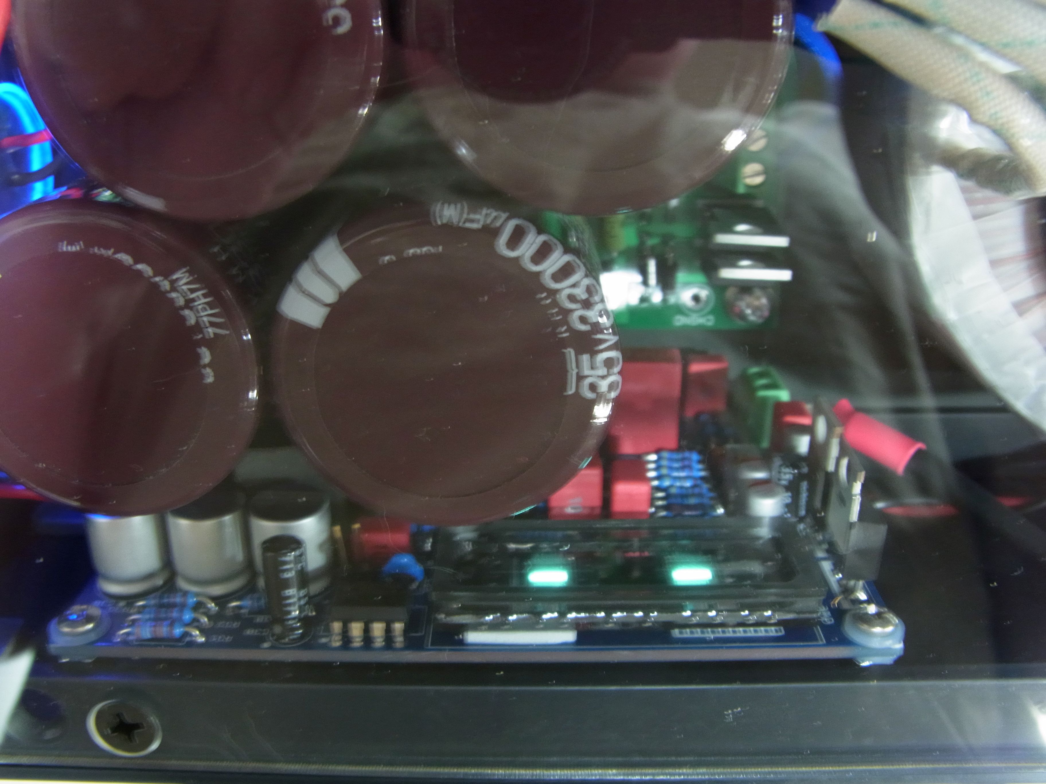
Here is the parts list (BOM) in .XLS or .PDF. Note that even though the schematic shows 22,000uF caps, I used 33,000uF (because they would fit).
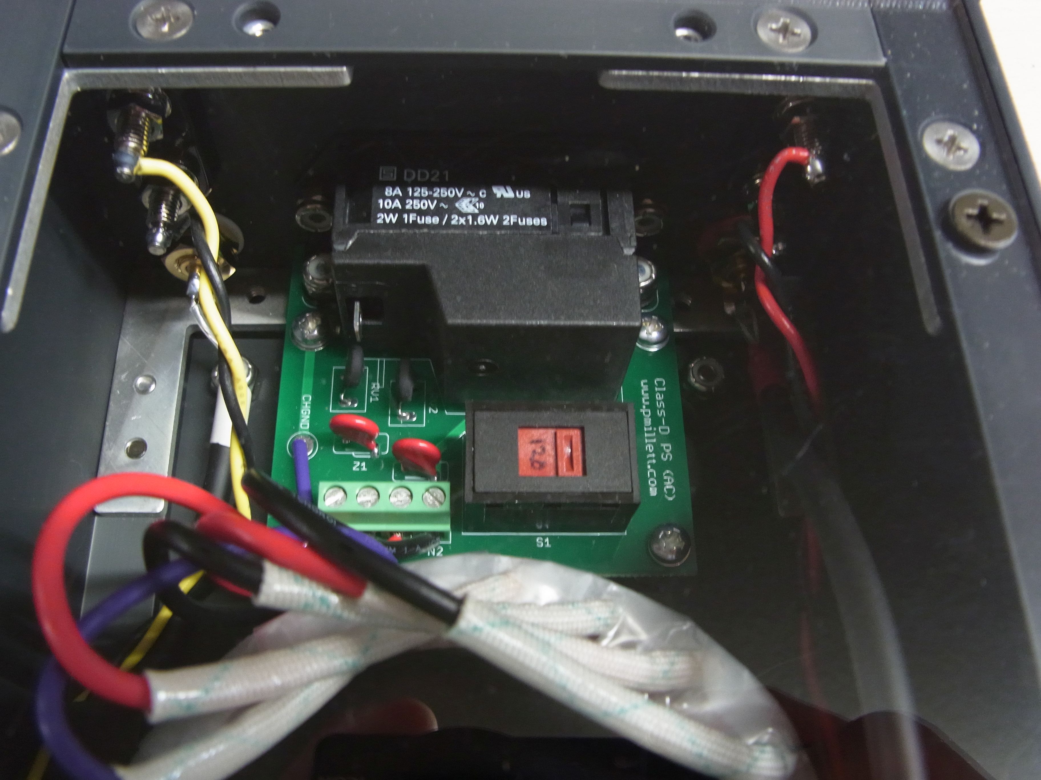
Putting it together (the chassis)
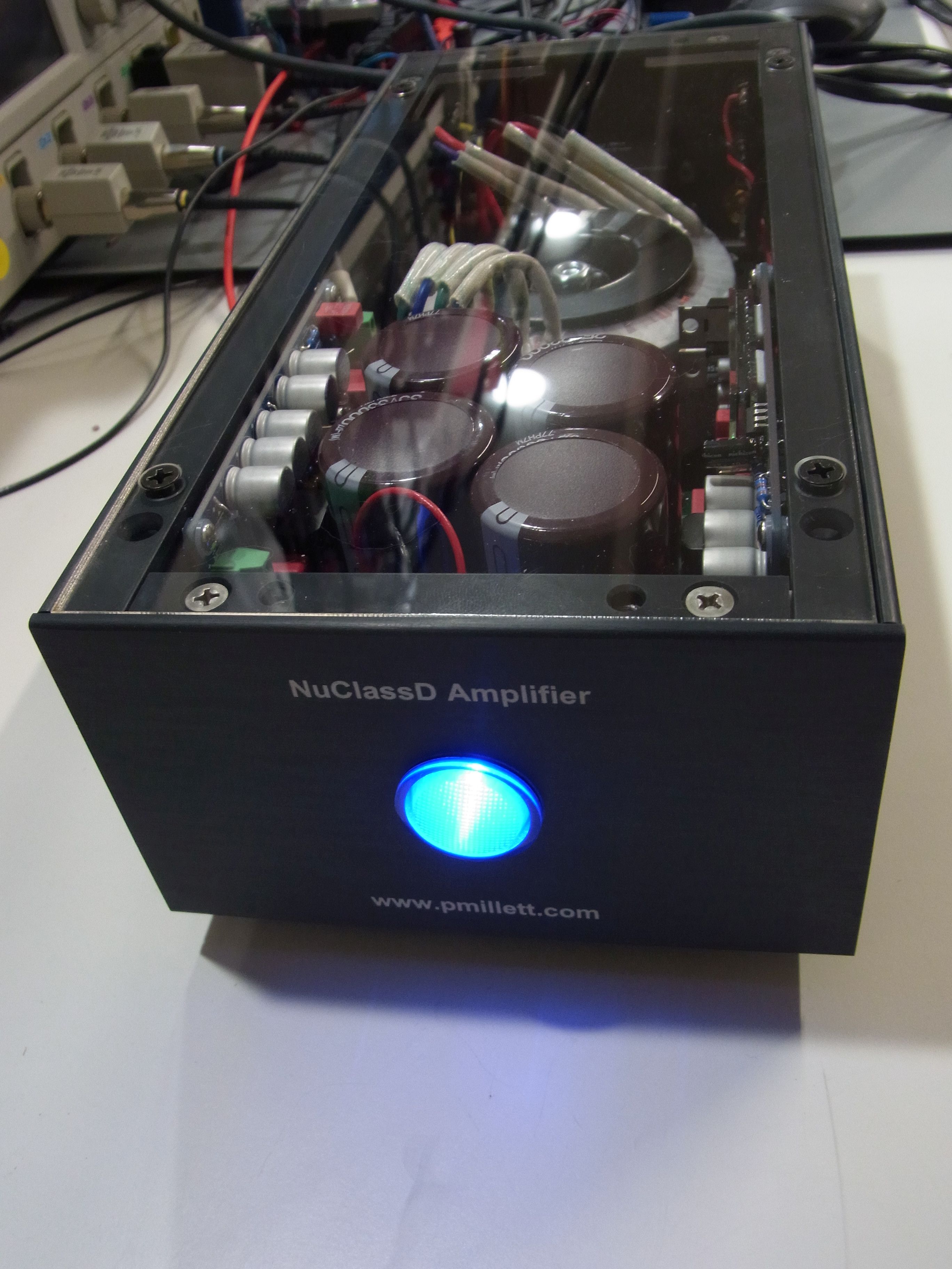
I had Landfall Systems build a box for a stereo amp, using two of the amp PCBs and the power supply shown above. Here are a couple of pics:
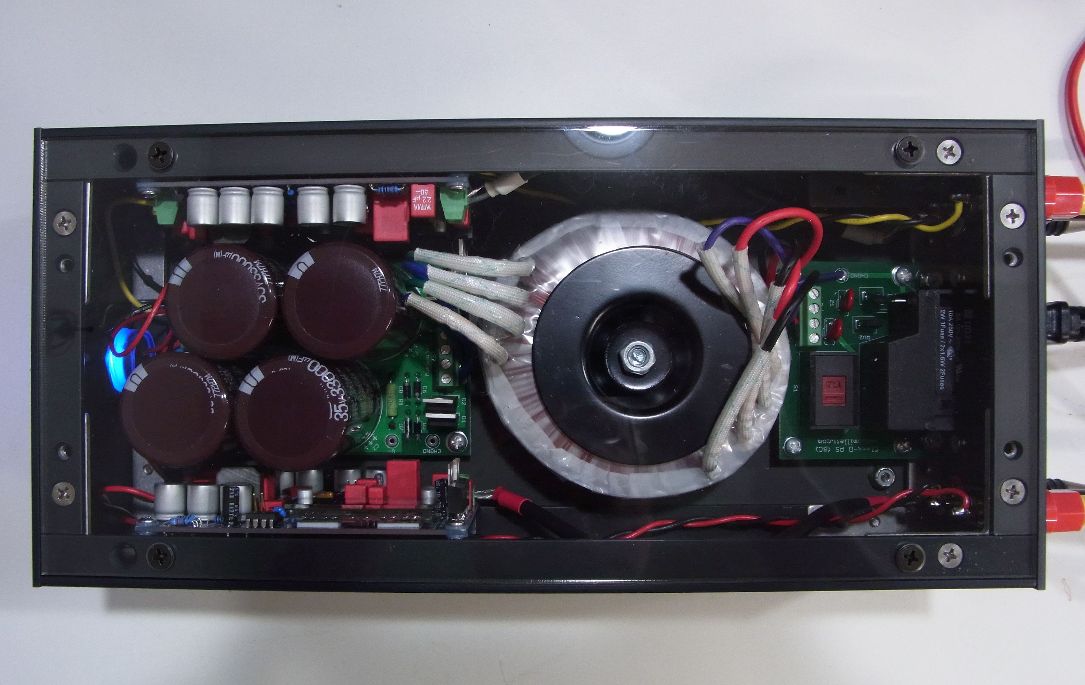
I put a clear plastic top on so you can see the glowing Nutube :)
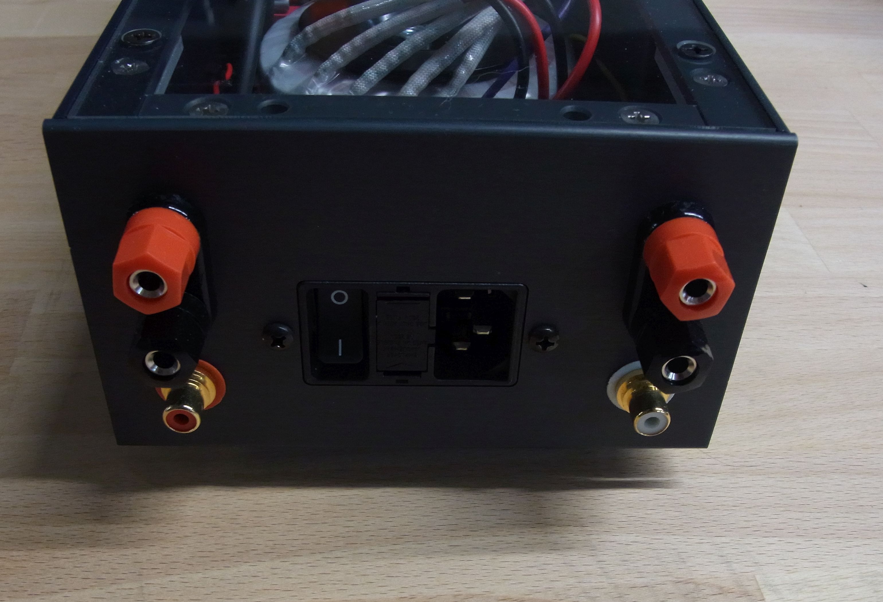
Landfall can build this for you. You can also download the mechanical CAD files (AutoCAD DWG and DXF files, zipped)
Measurements
My goal here was to build a hybrid amp that sounds - and measures - like a big single ended triode amp. I think I succeeded, though one could argue I should dial in a little more 2nd harmonic distortion. That is easy to do by changing the bias point or the plate load resistor of the Nutube.
Here are some measurements:
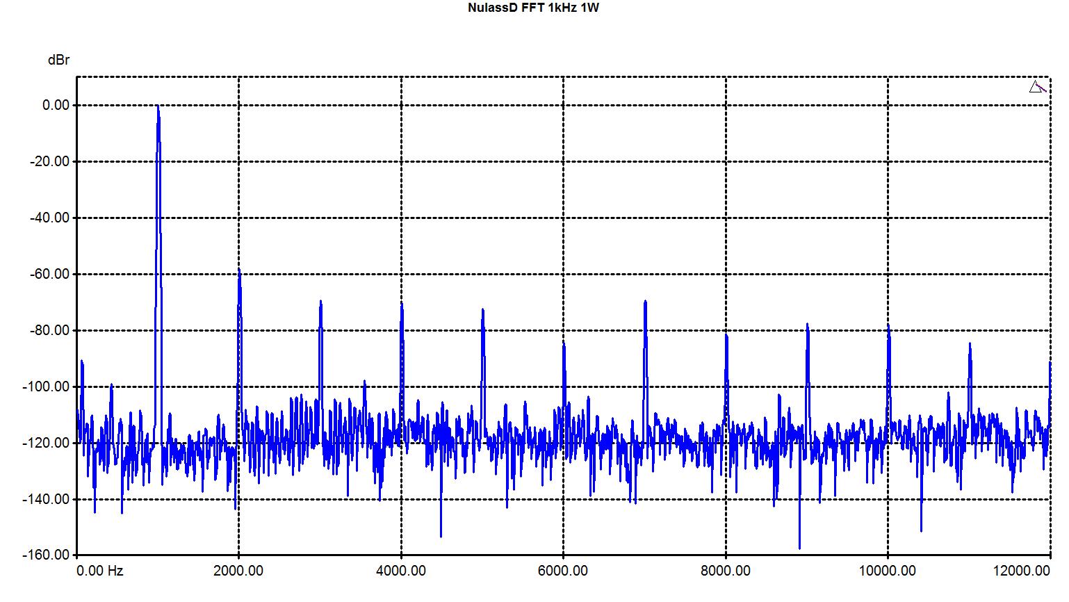
FFT at 1 watt (1kHz). Distortion is pretty low here so you see the 2nd harmonic is the biggest, but there are others present as well.
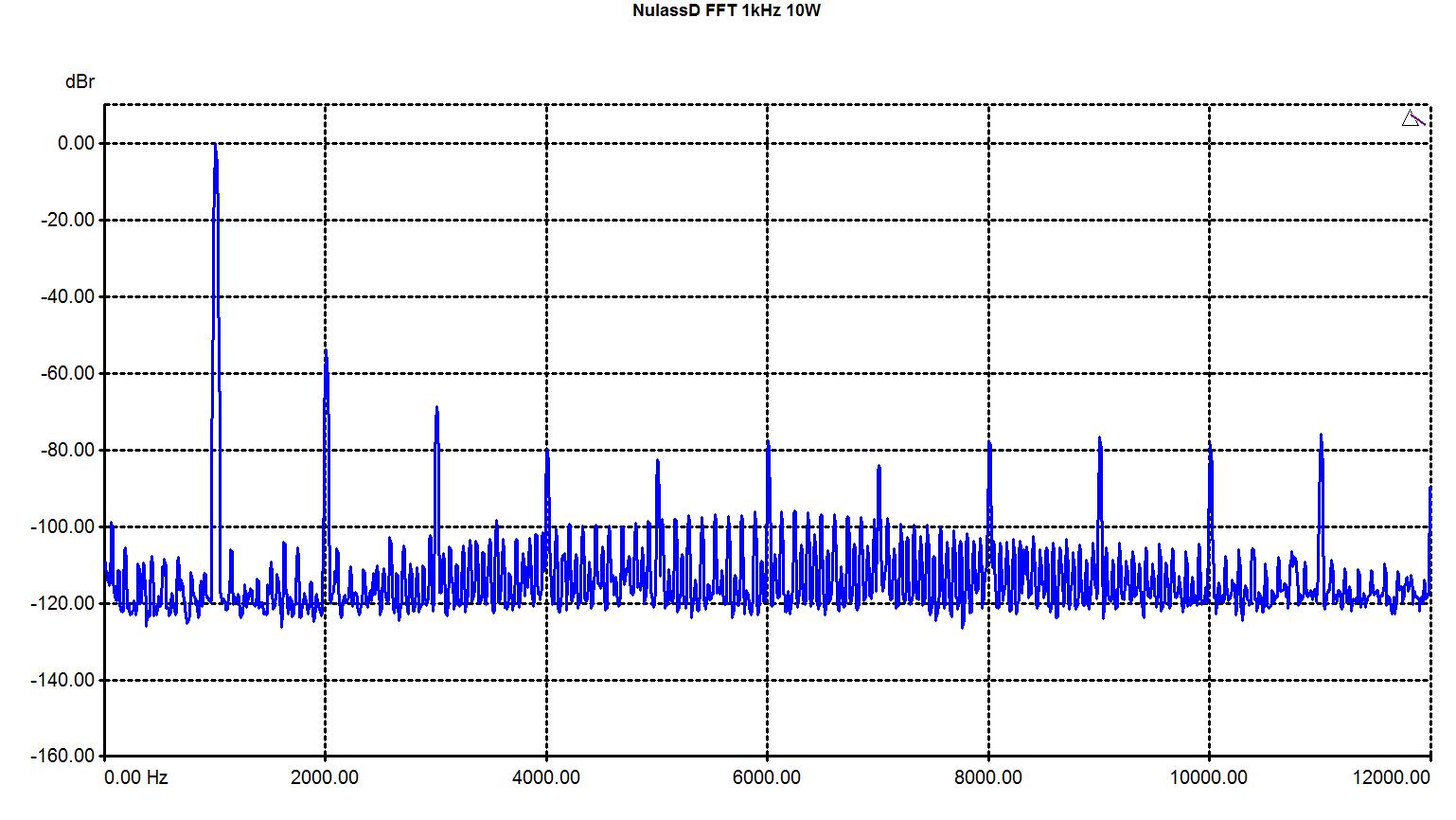
FFT at 10 watts. Not a lot different - the second harmonic is up a bit.
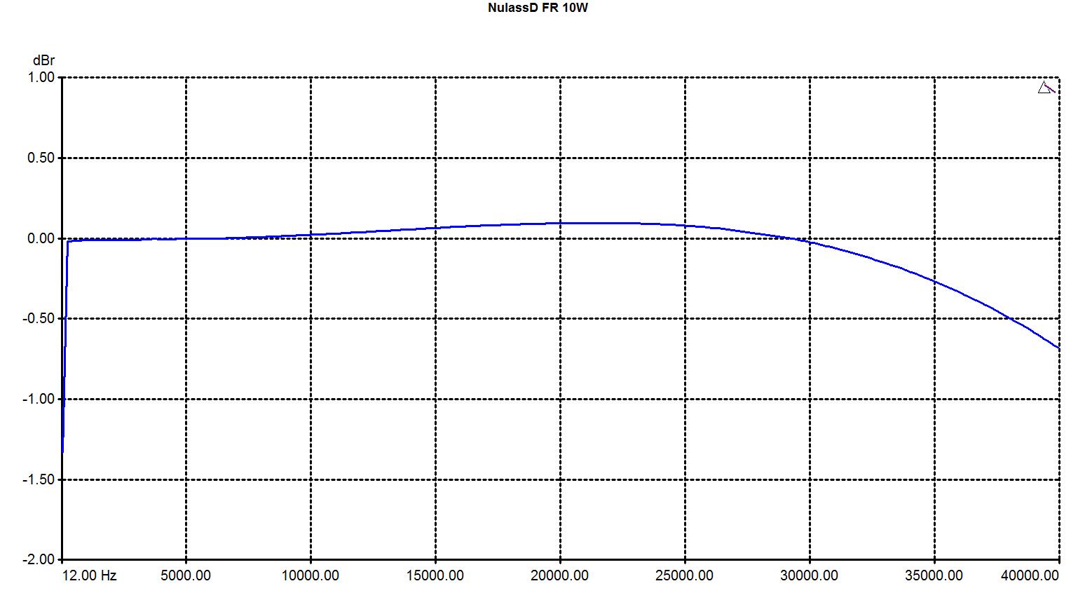
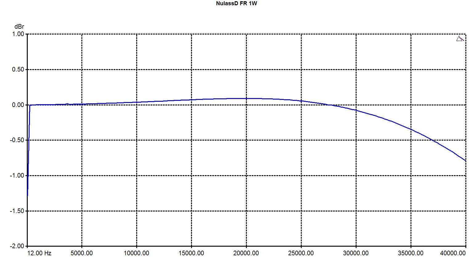
Frequency response at 10 watts, and at 1 watt. Note the scale. Flat from ~12Hz and down 0.7dB at 40kHz.
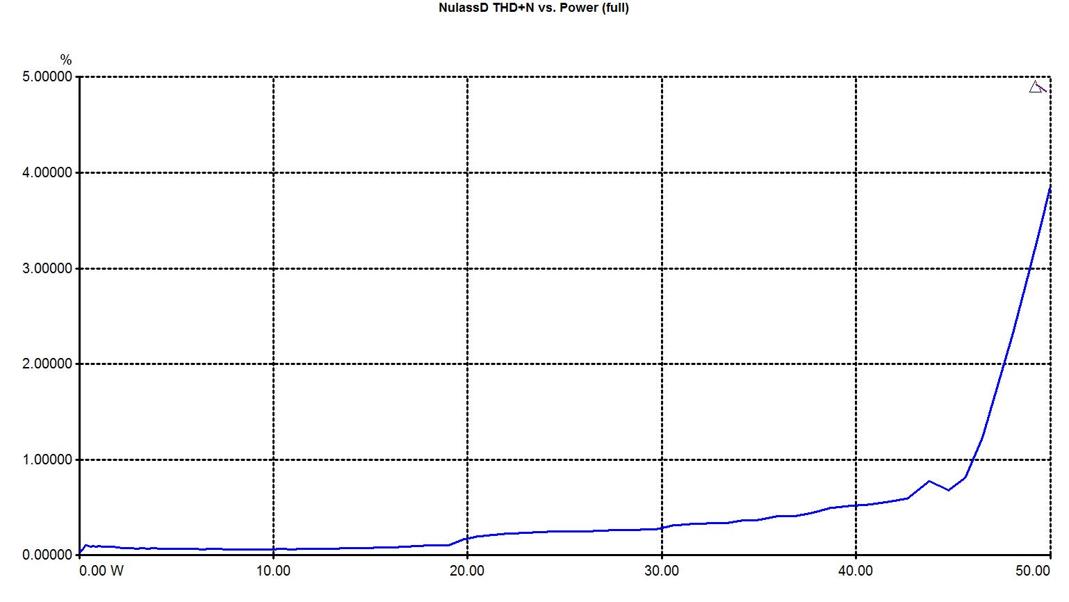
THD vs. power over the full power range. Clipping (5% THD) is at about 50 watts, but onset is gradual.
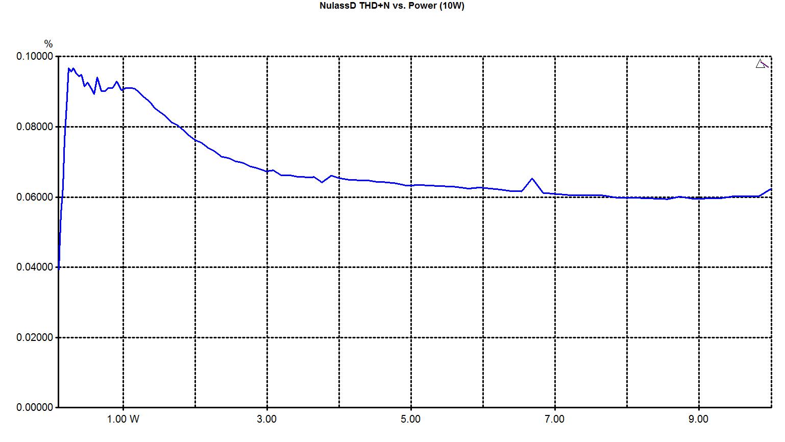
A zoom of THD vs. power stopping at 10 watts. Basically 0.06% THD, with the noise floor just barely popping up at the left.
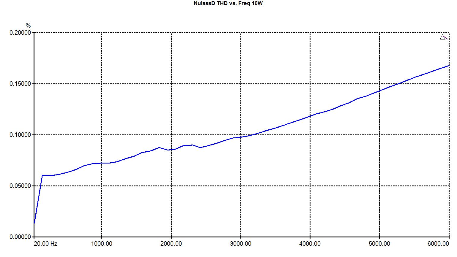
THD vs. frequency at 10 watts shows a modest slew rate induced THD increase with frequency.