NEW - Oscillation of input buffer
Under some conditions, the 2N7000 input buffers (Q1 and Q3) may cause high frequency oscillation. There are two solutions: Insert a gate stopper resistor of around 1k in series with the MOSFET gate, or replace the 2N7000 FETs with 2N3904 NPN transistors. If you use 2N3904 then you should also change R2 and R10 to 10k.
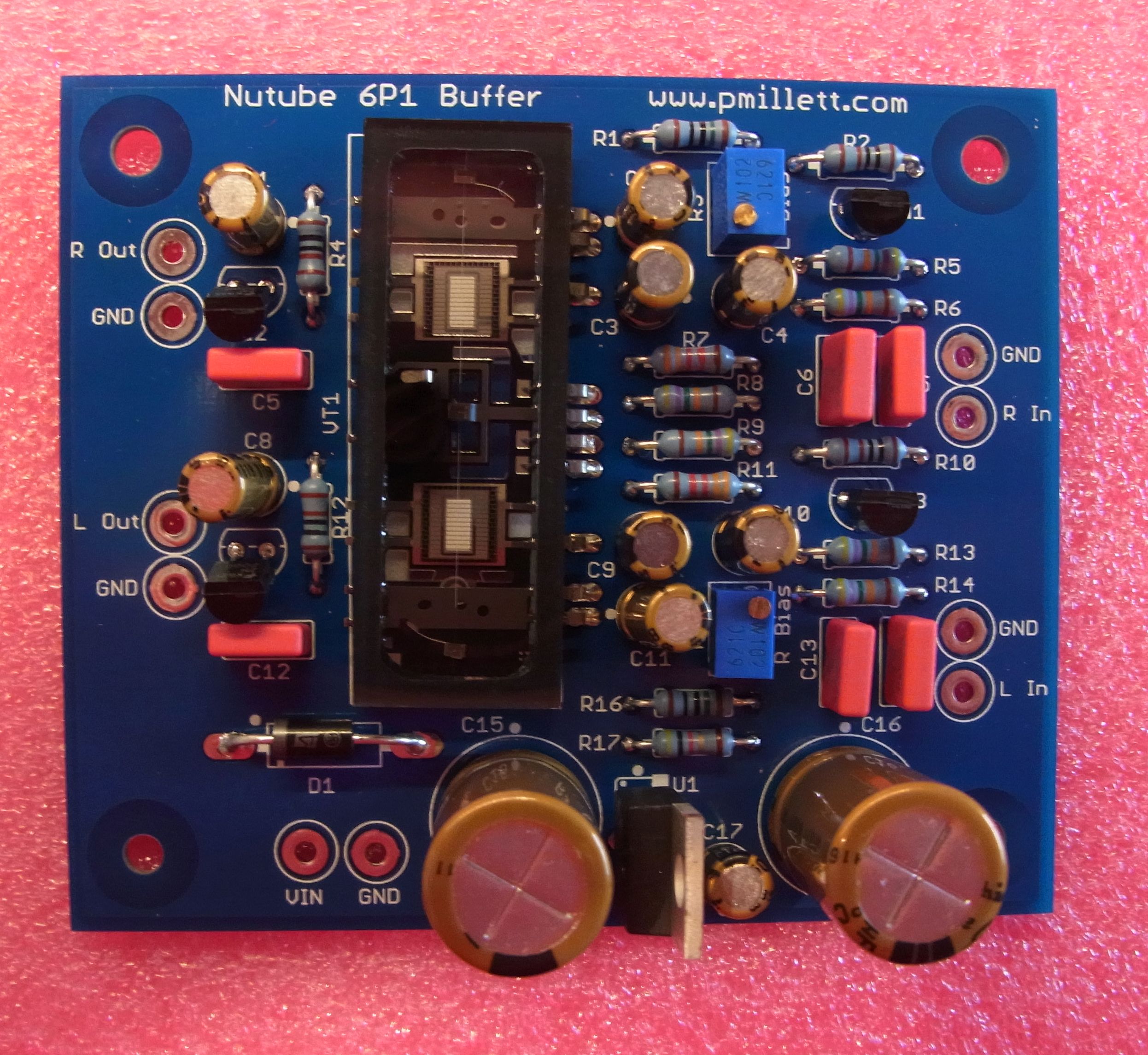
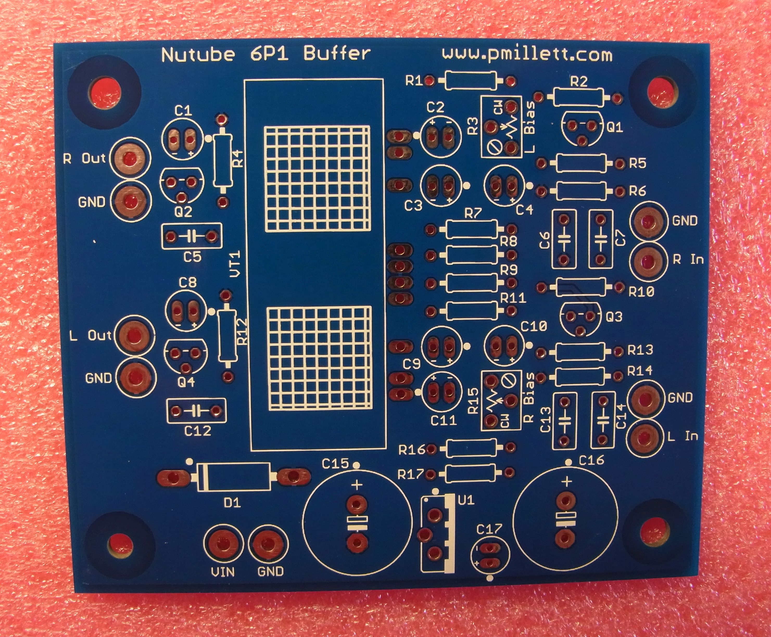
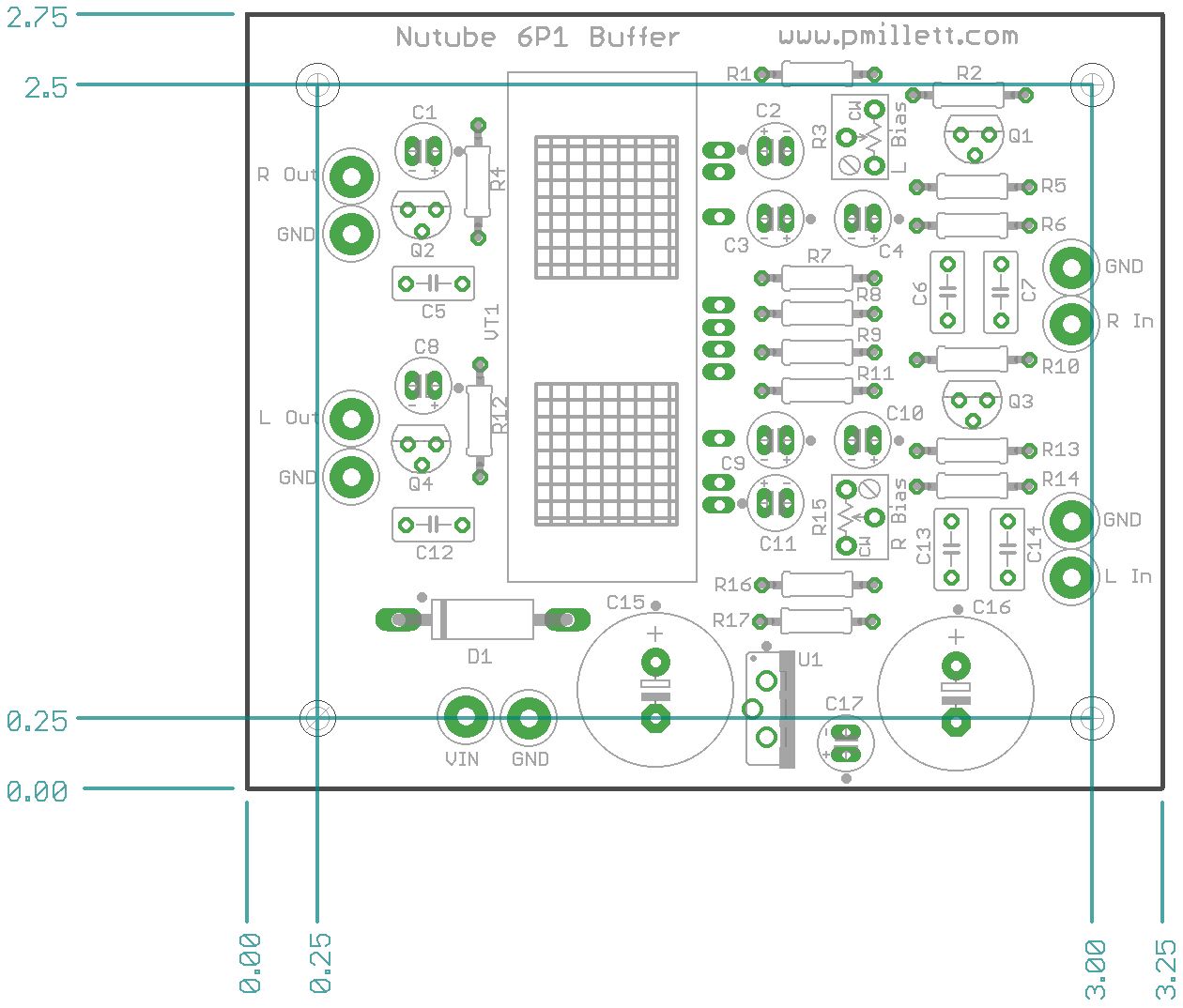
I have had some requests for a simple buffer PCB using the Korg Nutube 6P1. So, here it is...
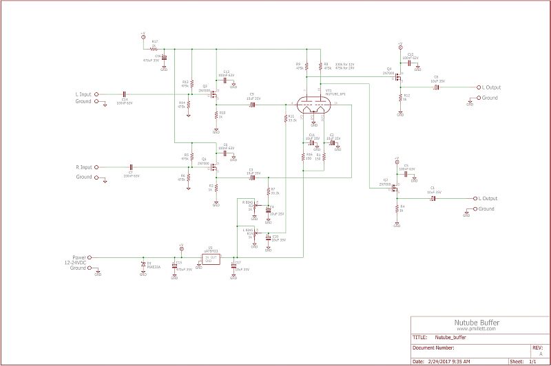
Here is the schematic in PDF form, and the parts list (BOM) in PDF or XLS. Also, I made a Mouser BOM with all the parts (the access ID is bbee51d8dc if the link doesn't work) . The total BOM cost is $66.10 from Mouser, and $50 for the PCB plus Nutube 6P1 from my eBay store.
This board uses each half of the 6P1 (it is a dual triode device) separately, to give you a stereo line amplifier.
The idea here is to implement a simple single stage amplifier using the Nutube, so people can evaluate it in an audio system.
You can get more details about the Nutube at www.nutube.us. I'll be selling the PCB, along with one of the Korg 6P1 Nutube devices, on my eBay store.
Most interest in using this device is to provide "signal processing" - specifically, to make a solid-state amplifier sound more like a big single-ended tube amplifier. I have built a Nutube / class-D hybrid that did exactly that... it really did measure and sound a lot like a big SE tube amp. Whether that's your "cup of tea" or not I leave up to you...
The board runs from a power supply of 12V DC typically. It will work anywhere from about 5V up to 30V using the components specified.
Since the 6P1 is usually operated in class A2, with some grid current, the board has MOSFET followers to drive the grids. Since the 6P1 has relatively high plate resistance, I also put MOSFET followers at the outputs. If you are driving something that has high input impedance (> 100k or so), you can not populate the output buffers and jumper around them if you want.
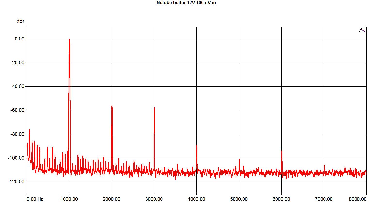
Powered from 12V, the buffer has a gain of about 6x. You can adjust the bias to change the distortion characteristics - minimum THD with 100mV in (and ~600mV out) is about 0.2%. An FFT under these conditions shows typical single-ended triode characteristics. Note that if you skew the bias you can change the relative proportions of even and off harmonics; this was taken with the total distortion minimized.