A PL-177 Single-ended amplifier
I've been looking for a transmitting tube that could make a decent audio amp, without using outrageously high voltages and/or uber-expensive output transformers. I finally found one: an oddball called the PL-177.
The only place I can find reference to the usage of the PL-177 is in a Vietnam-war era field transmitter, the PRC-47. I think it was marketed to hams as well, but I don't think it ever caught on.
The PL-177 is similar to the 4-65 tube. But it is a pentode, or more correctly a beam pentode. It adds a supressor grid which is constructed of vanes to funnel the electron stream into beams. It comes in normal (PL-177A) and military (PL-177WA) versions. It also has a close cousin, the (PL-) 6549, which is essentially the same tube with a conventional suppressor grid. I tested all three... the PL-177A and PL-177WA seem completely identical. The 6549 worked well but was slightly less linear.
One of the tubes came with a nice datasheet and a Penta catalog. I scanned the datasheet and the relevant catalog pages to download (PDF file).
Since the datasheet only has constant-current curves, I ran my own curves, both in pentode mode with a 300V screen grid, and in triode mode. You can download them and the raw data (.xls file).
Initially, my hope was to use triode mode:
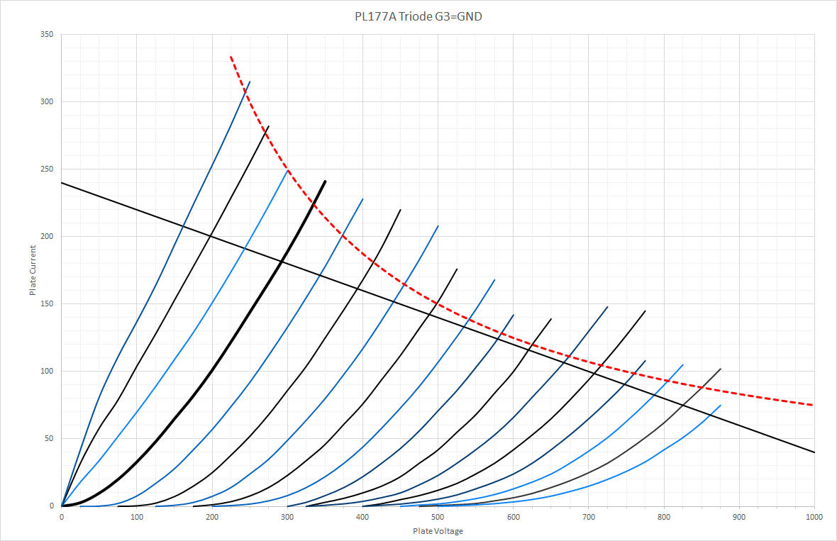
Pretty nice curves. But unfortunately, the screen grid grabs much of the current, and limits dissipation to only a few watts. I melted a couple of screen grids trying this. So, to pentode mode we go...
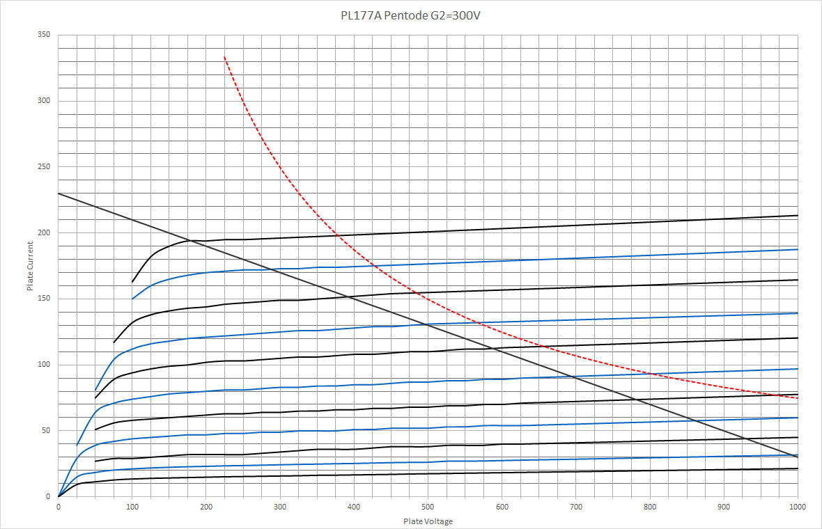
Ignore the waviness of the lines, it is rounding error. This is a darn linear pentode!
Here is the schematic of the amp I designed (or download it in PDF):
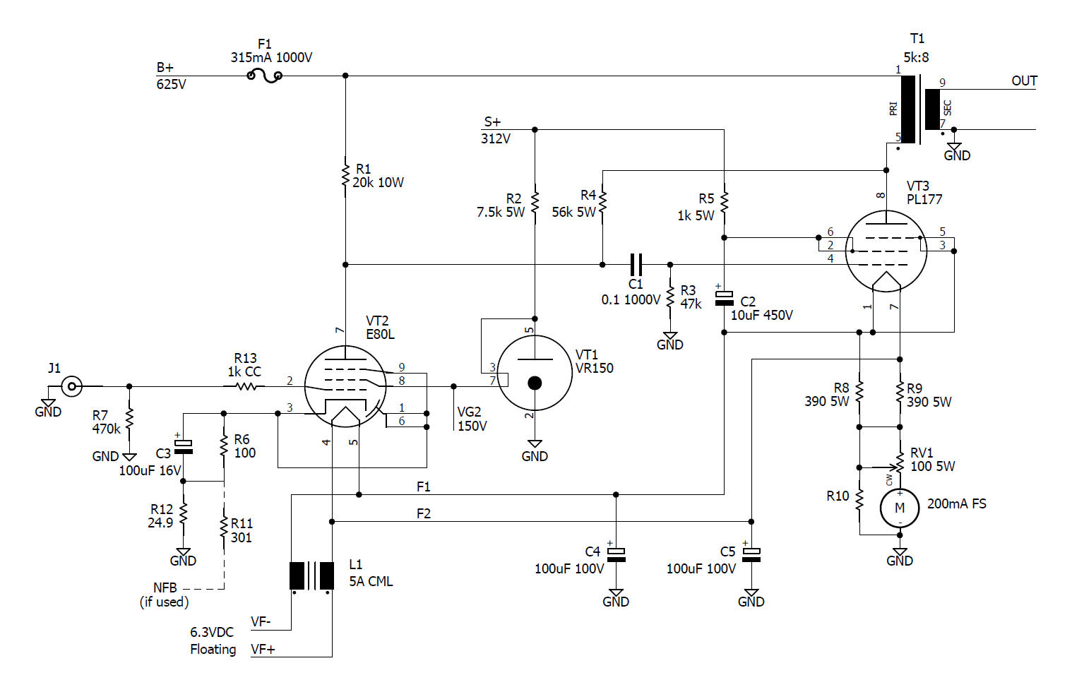
Very simple... a high gm pentode (E80L) cap coupled to the PL-177, with cathode bias in class A1, This is one of the very few transmitter tubes that works well in A1! B+ is about 625V, and the screen is at 1/2 that, or about 312V. Note that you need to use a driver pentode that is rated for fairly high plate voltage here... the E80L is perfect.
Since we are running in pentode mode, some form of negative feedback is pretty much mandatory. I used plate-to-grid feedback (actually plate-to-driver-plate) to make the tube act almost like a triode. In addition, I added just a little loop NFB to help keep the output impedance down.
I used a modestly priced 5K SE output transformer from Hammond, the 1628SEA. It needs to support the 100mA bias current...
The amp is biased for about 100mA plate current. It can output about 15 watts at 5% THD.
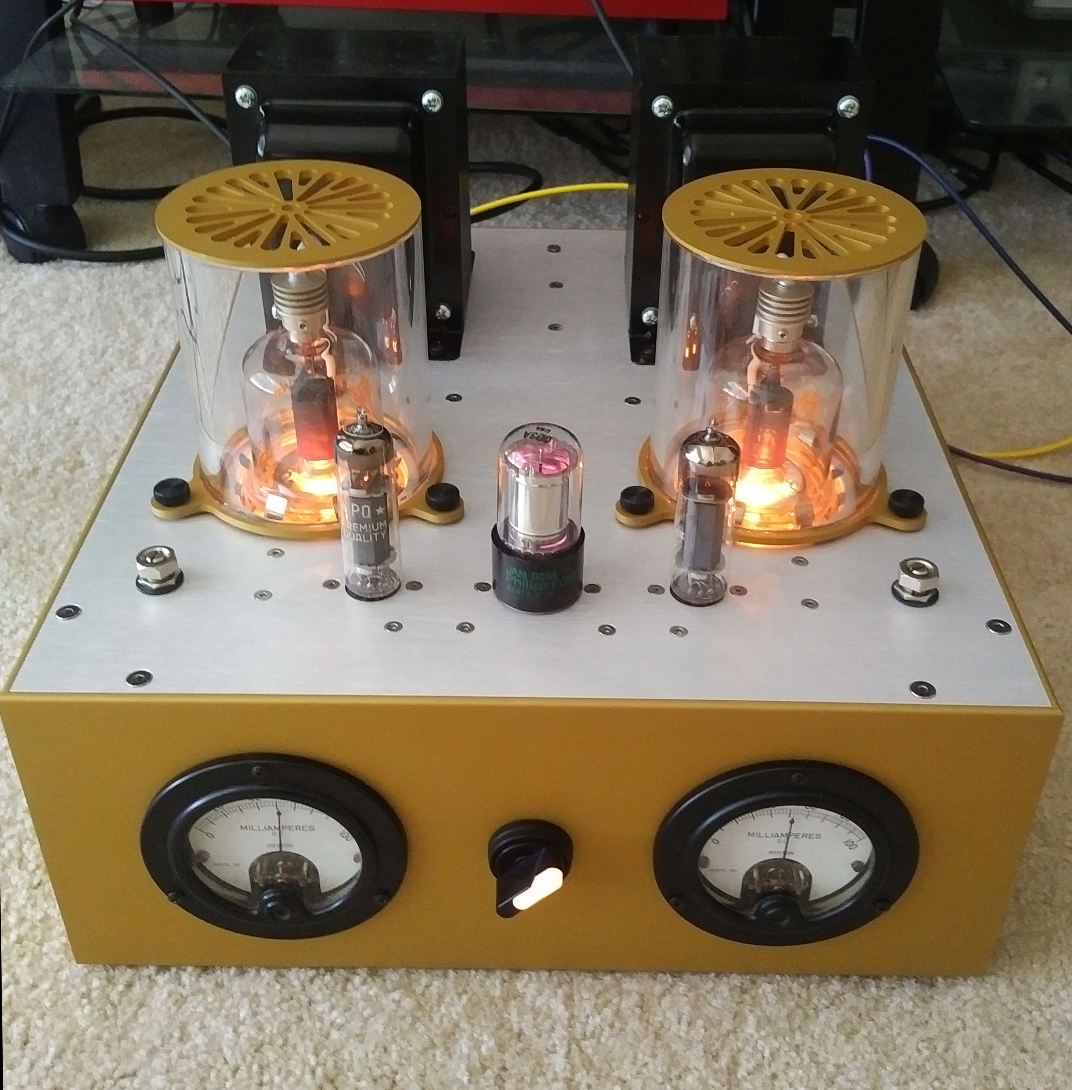
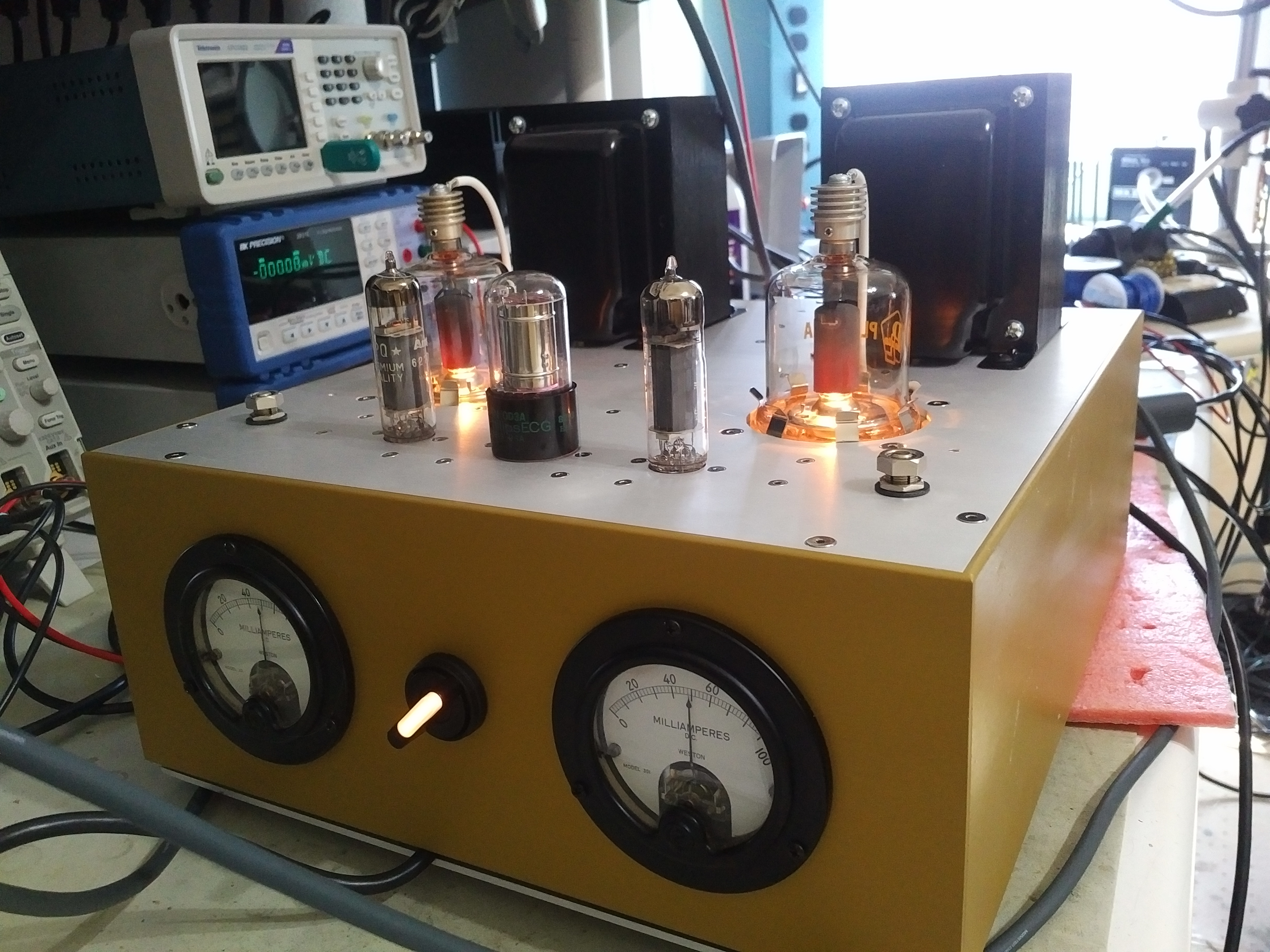
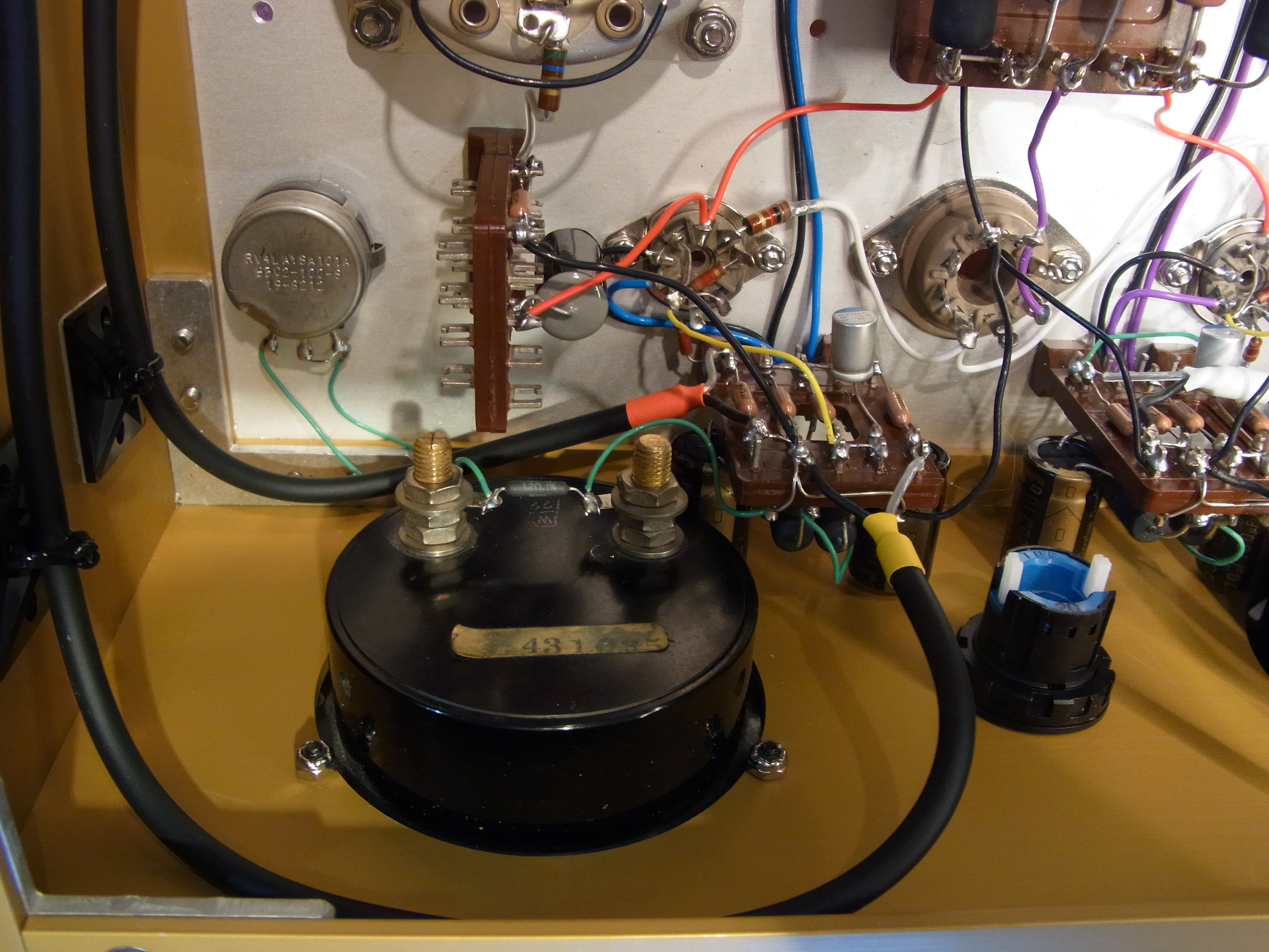
Construction
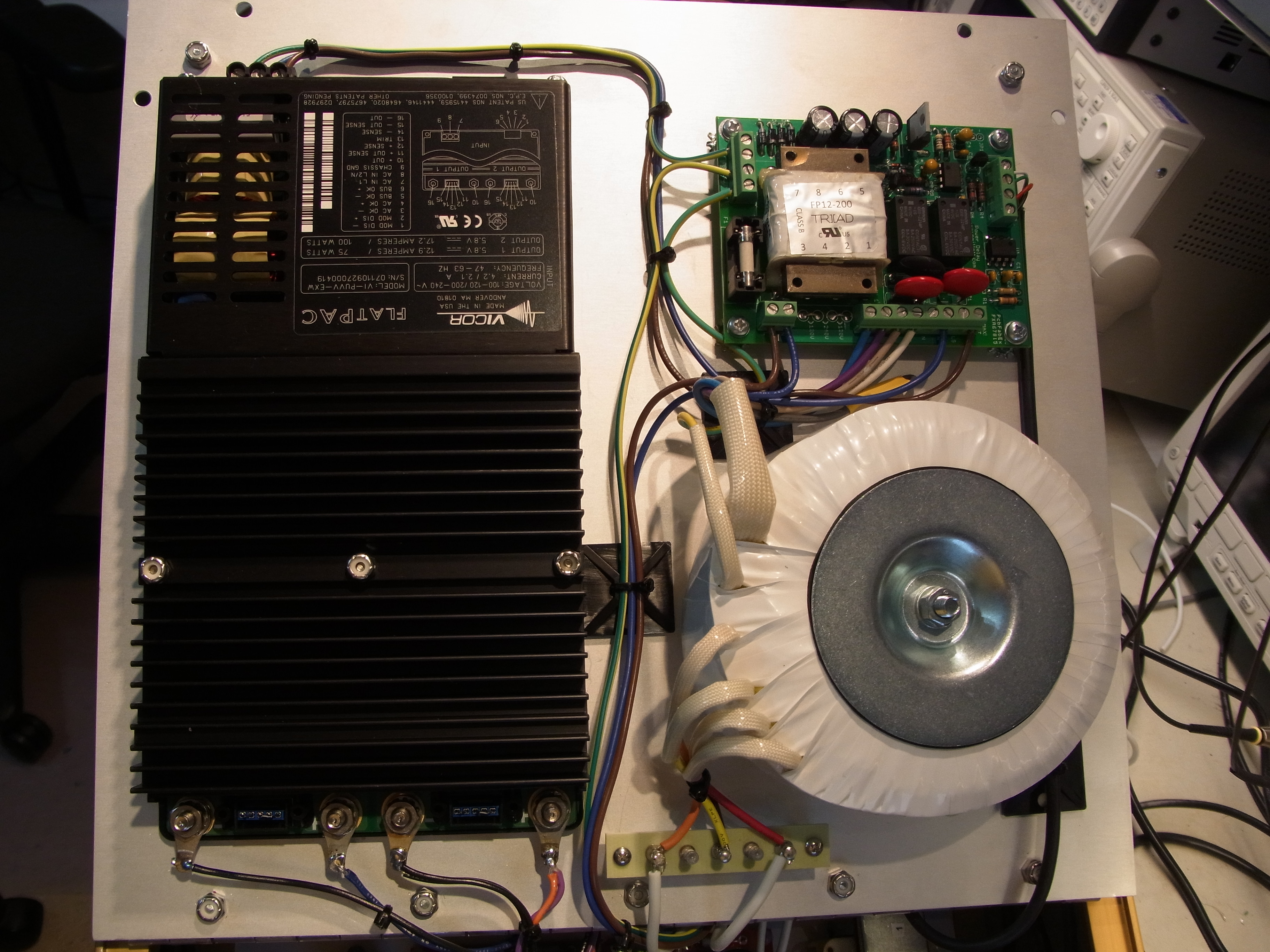
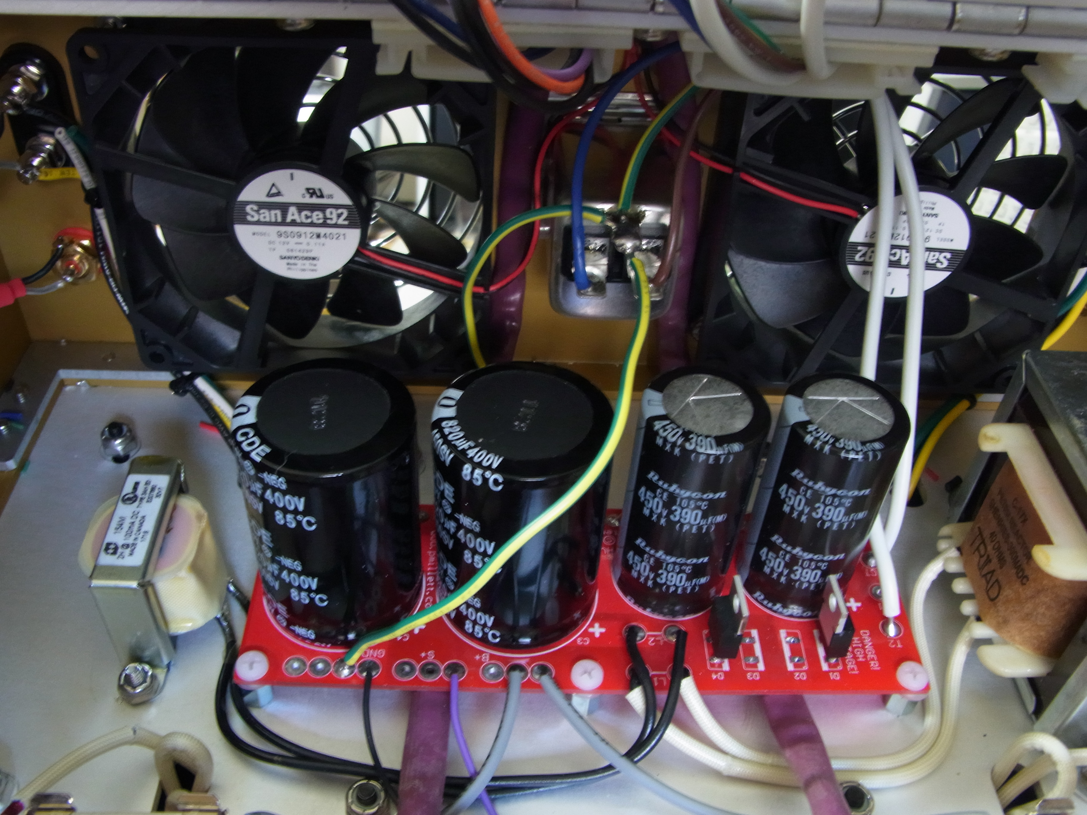
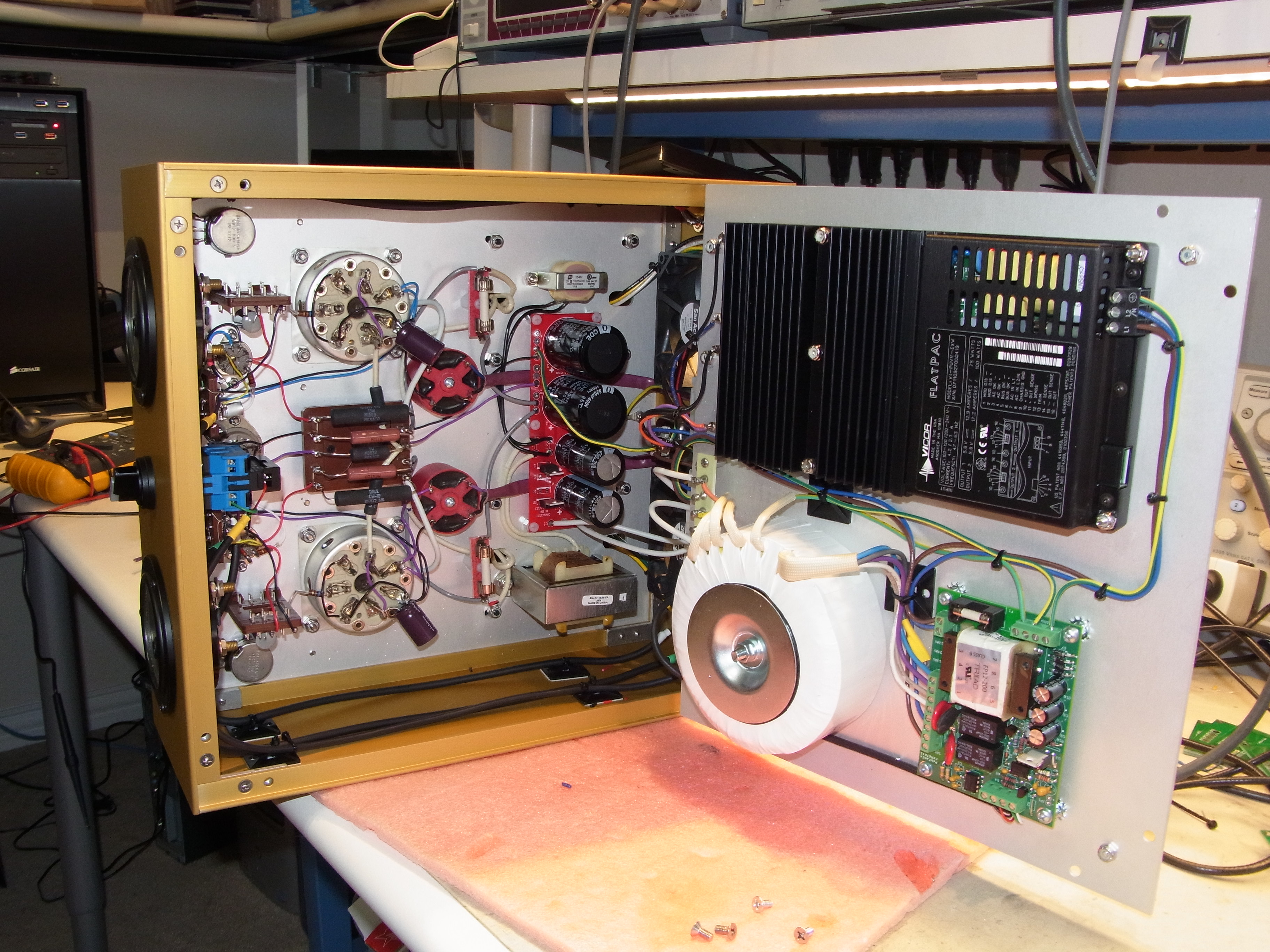
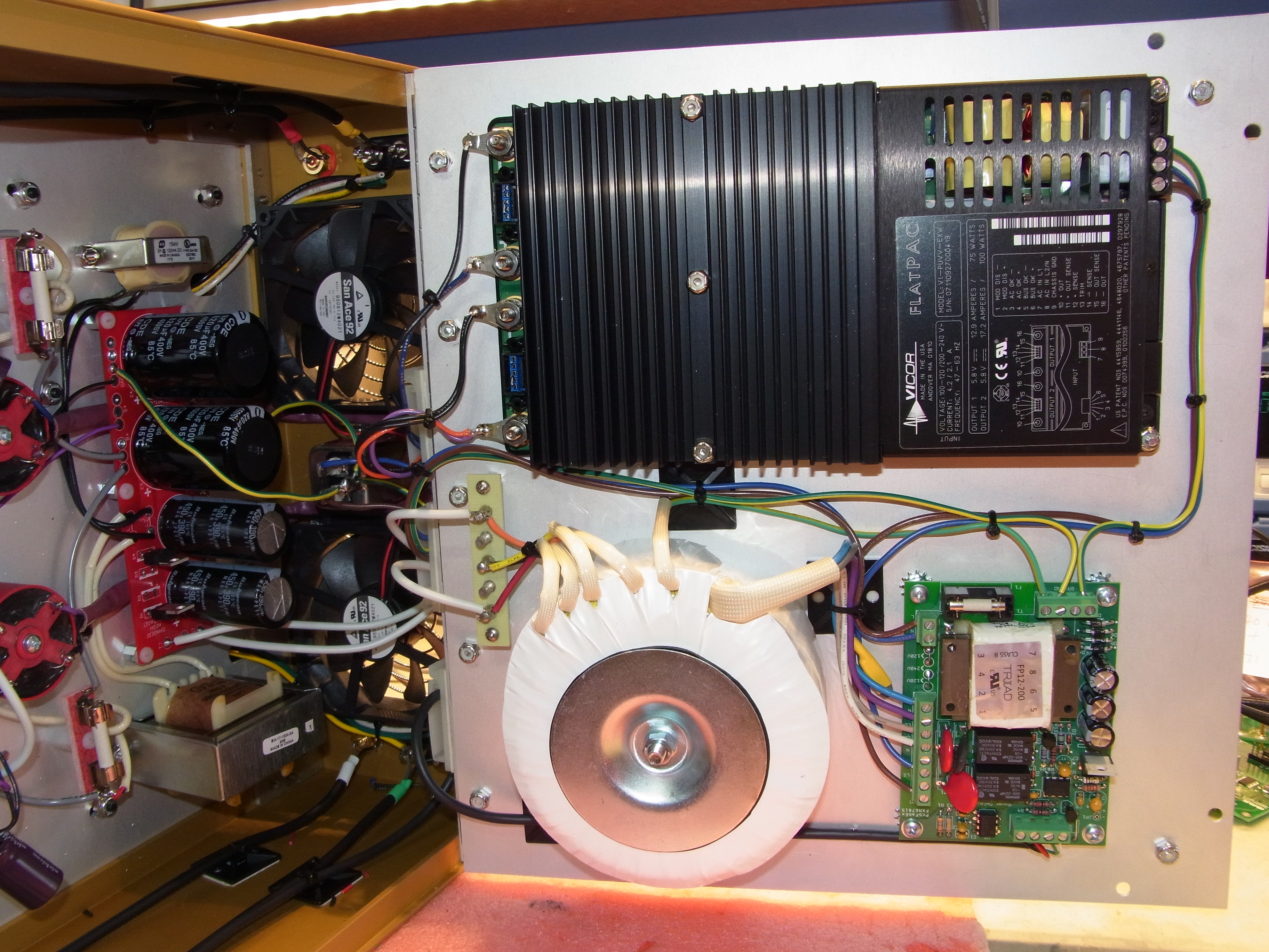
For power, I used a toroidal isolation transformer (Triad VPM240-1040) wired to output 240V, feeding a voltage doubler. I used one of my power supply PCBs (shown on the 807 P-P amp) to do this. Two smallish chokes are used for filtering - a Triad C-17X (1.5H 300mA) for the B+ and a Hammond 154M (2H 100mA) for the screen. The +312V screen supply is derived from the doubler "center tap". Sorry, no schematic or BOM, but it's simple enough that you can figure ot out from the photos. If not, you probably shouldn't be building an amp like this anyway...
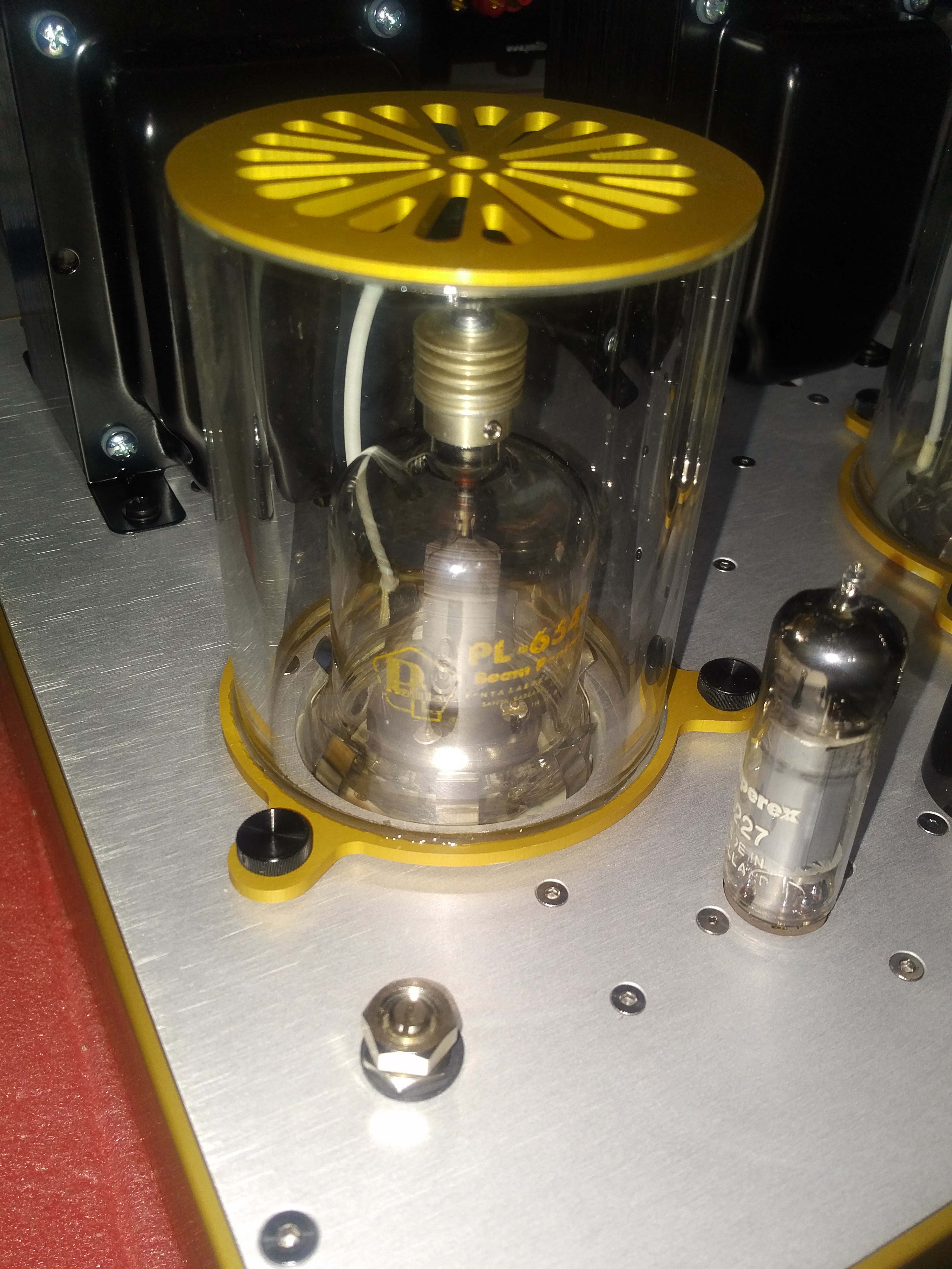
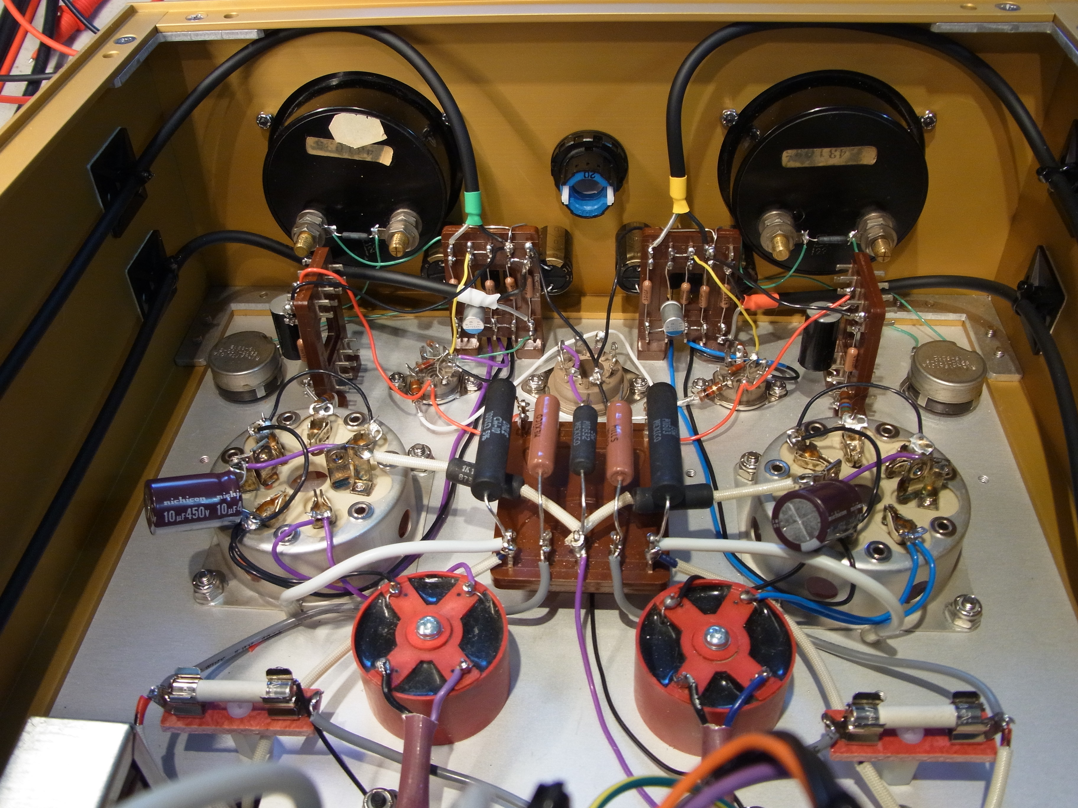
Notice the two large fans. They are 12V low-noise fans, running off of the 6V filament supply. They are very quiet, and draw air from the rear of the amp. The air is exhausted through the tube sockets into the glass chimneys, which direct air over the tubes and the heat dissipating plate caps. I am not certain this is necessary, but with cherry red plates I thought it would be wise.
The chimney was made by gluing two fabricated aluminum parts (machined by Landfall) to a big "sight glass" borosilicate glass tube I found at McMaster-Carr - expensive (~$50) but massive.
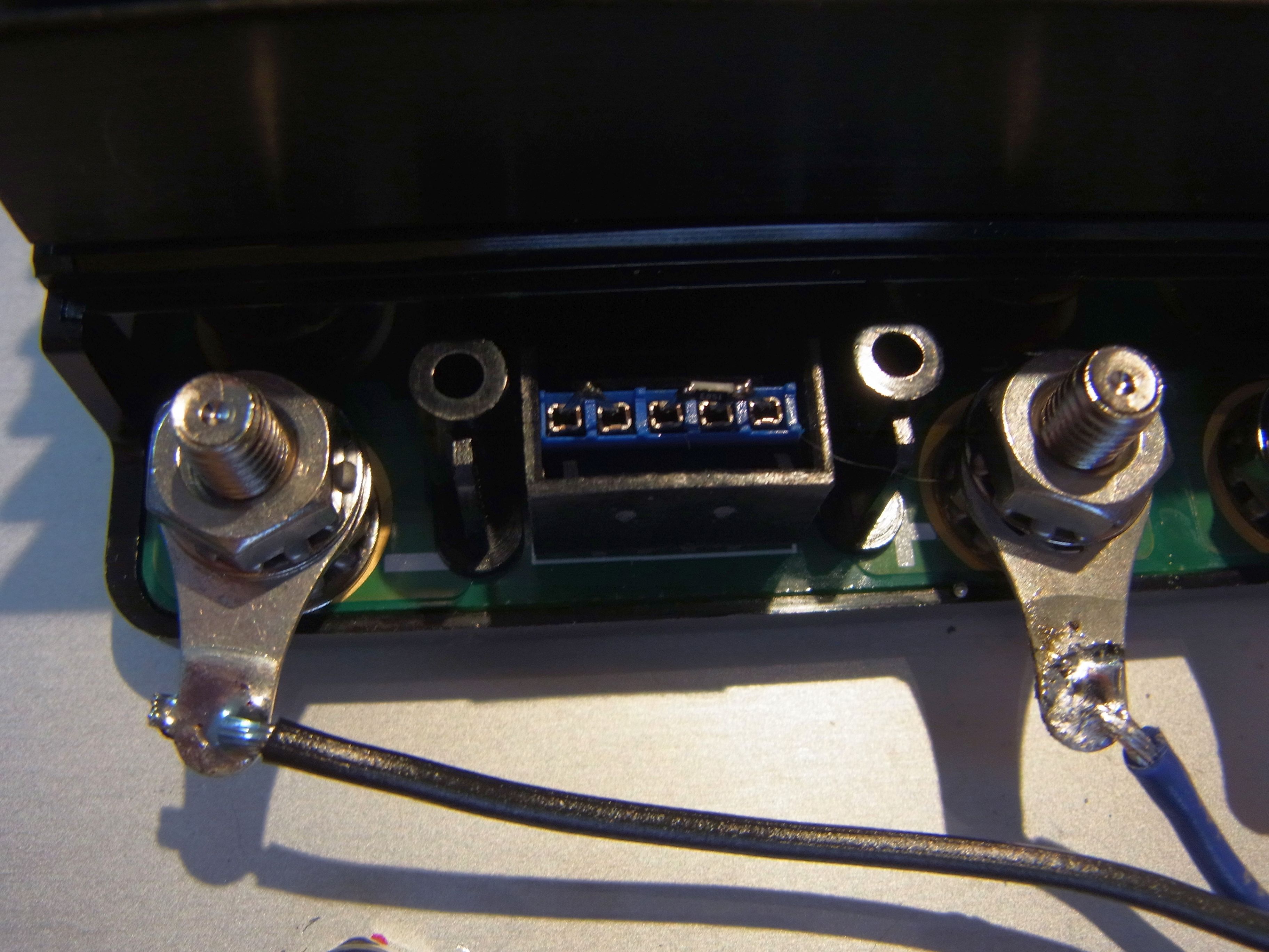
Both the driver heater and PL-177 filament are connected together and are powered from a floating switching power supply. I found a new Vicor supply that had two isolated 5.6V outputs - I used a resistor (small SMT part seen below on the trim connector) to trim the voltage up a tad to 6V. Each output feeds one channel of the stereo amp.
Since this is a directly-heated power tube, and all solid state rectification, I wanted a circuit to delay the application of B+ until the tube has had time to heat. So, I designed a power delay circuit to do this. You can see it in the photo above next to the toroidal transformer. There's details about this circuit on it's own page.
I built the amp in a chassis made by Landfall Systems. I made the bottom hinged, so you can open up the amp like a book, since I mounted the power supply components tp the bottom of the amp. You can download a zip archive with the AutoCAD DWG and DXF files...
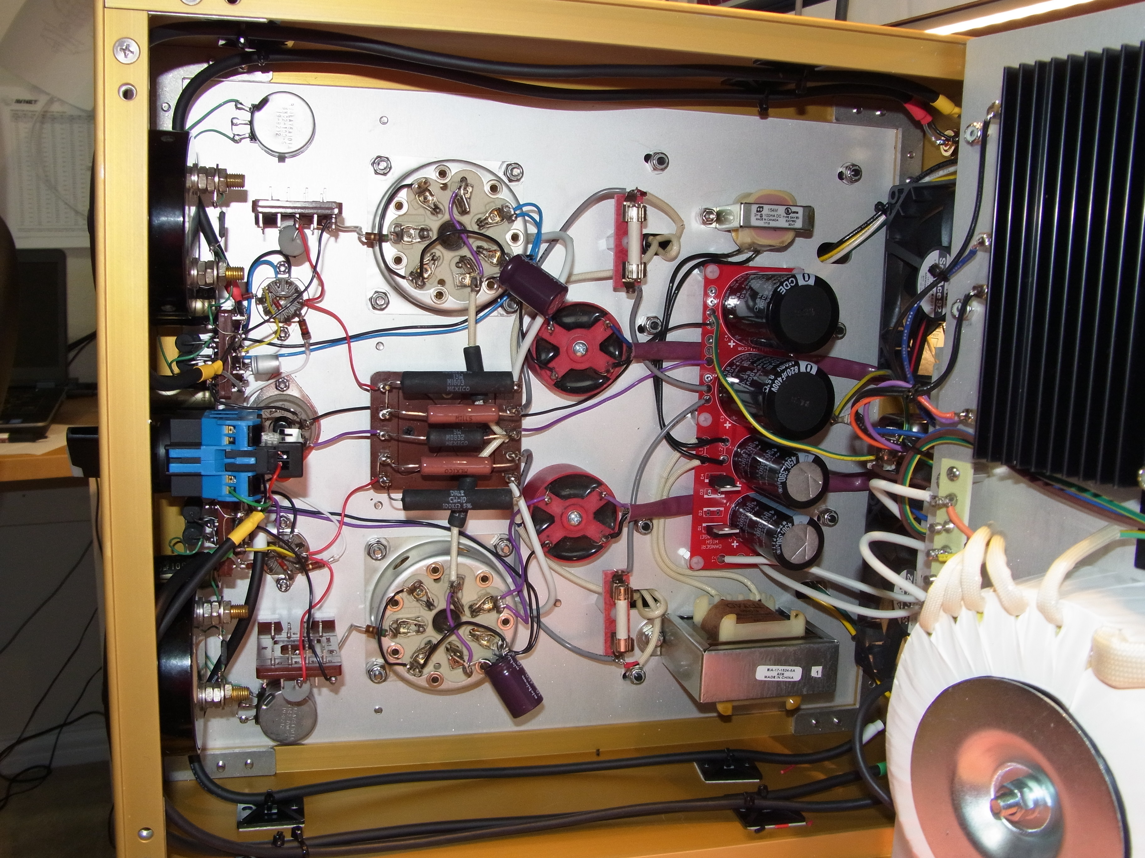
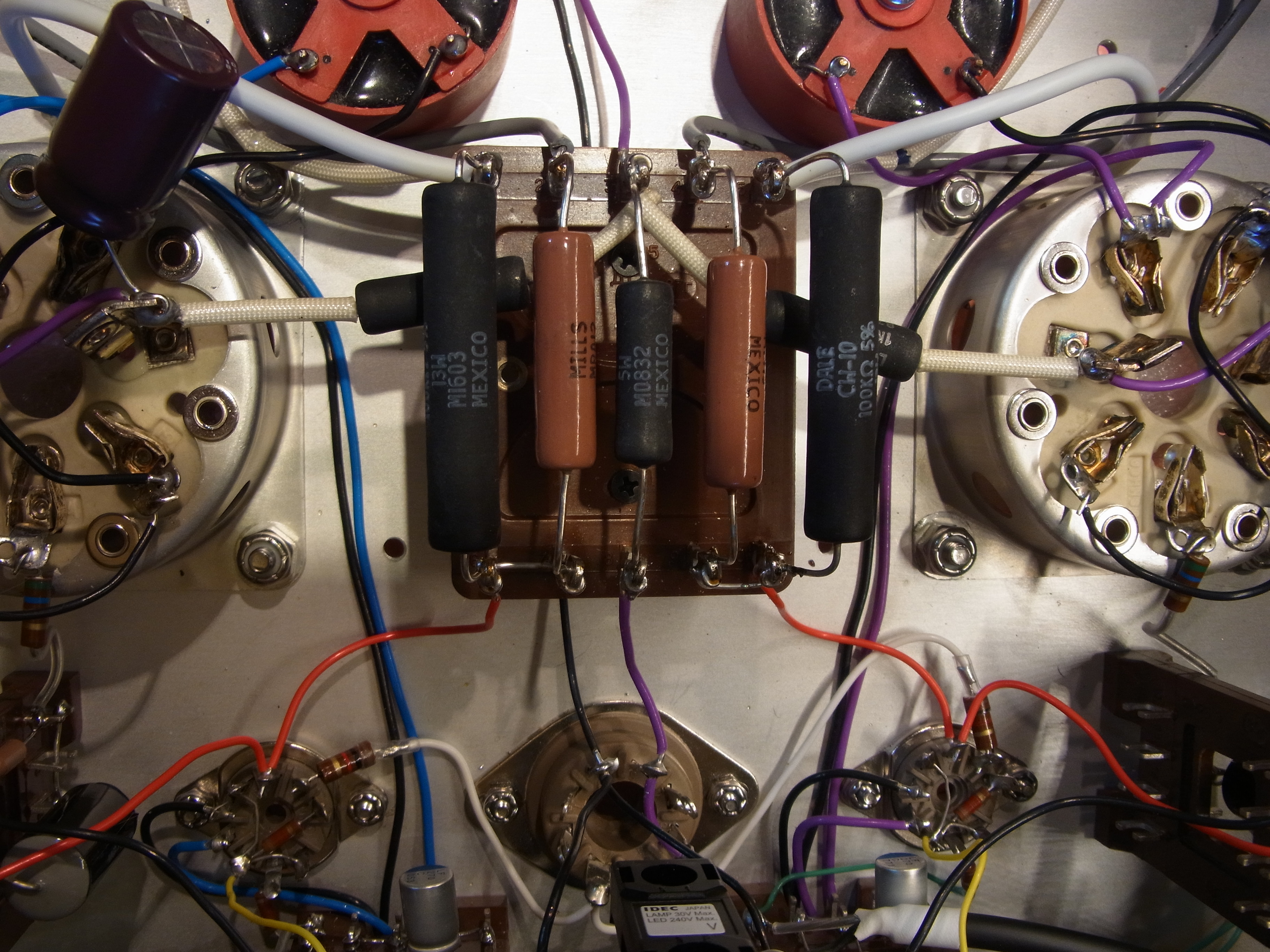
Components are mounted on the tube sockets, and on Russian terminal blocks bought off of eBay...
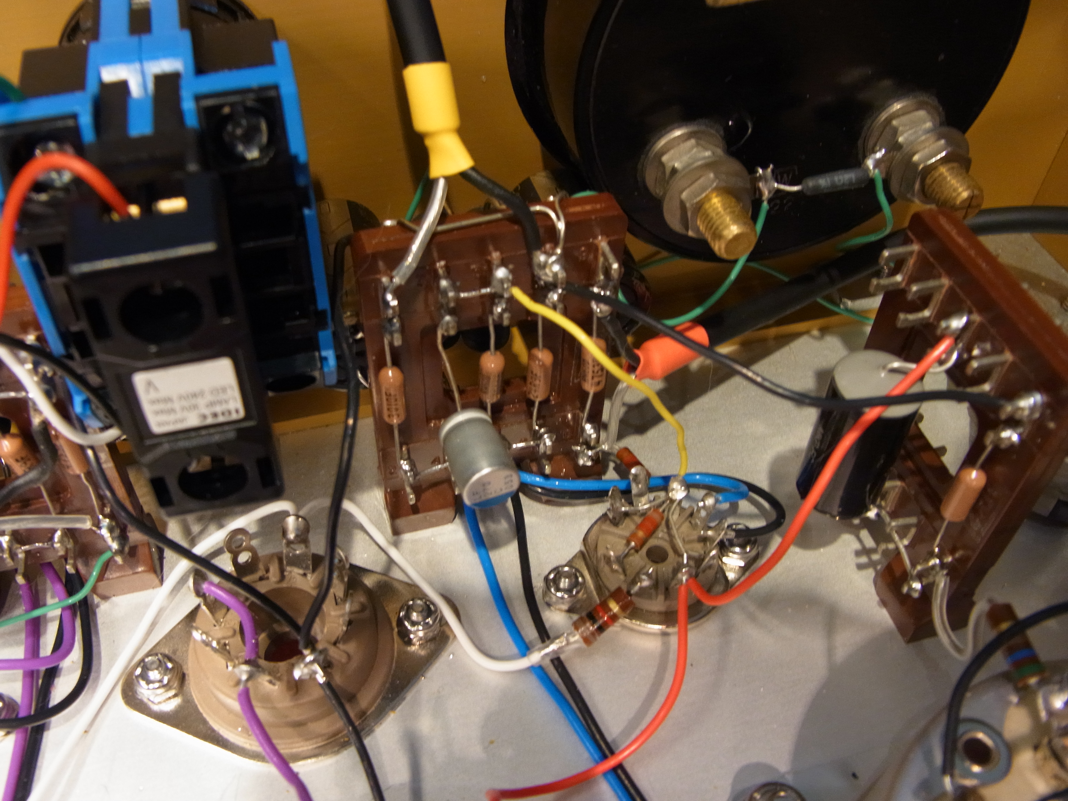
Notice the special high-voltage DC fuses. The power supply is very low impedance - if there is a problem, like a short in an output tube, the energy could be dangerous. So I inserted special DC-rated high voltage fuses in series.
The amp has adjustable cathode bias - a fixed resistor in series with a 5W wirewound potentiometer. Plate current is metered by monitoring the voltage across a portion of the fixed resistance.
Measurements and performance
As mentioned above, the amp can do about 15 watts into 8 ohms. This graph shows the output power and THD vs. the input voltage:
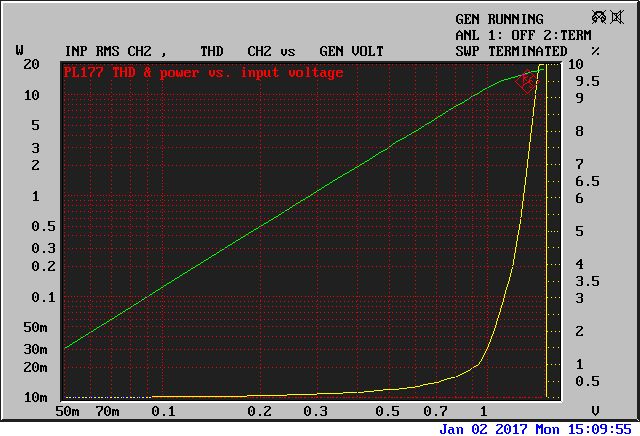
You can see THD is pretty low for an SE amp - about 0.05% at 1W, rising to 1% at about 10 watts.
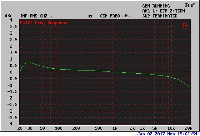
Frequency response is reasonably flat... the small LF bump (0.5dB) is probably due to phase shift in the OPT and the loop feedback.
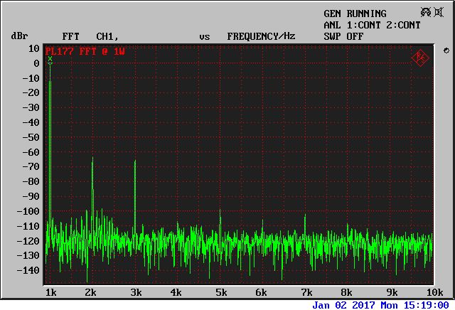
An FFT at 1 watt shows mostly 2nd and 3rd harmonics, and some "grass" which I assume is from power supply artifacts. It's 100dB down so no issue for me :)
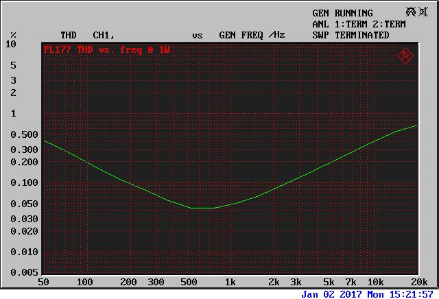
THD vs. frequency shows a typical increase in distortion at low frequency and at high frequency. I am sure this would be improved with a more expensive output transformer...