The "Engineer's Amplifier" - a distortion canceling push-pull amp using cheap TV tubes (!)
(Note that the photos are hyperlinked to full-size photos in grisly detail)
I am selling PCB's for this project. See my eBay store (seller "pmillett"). $50 each (hey, it's a big PCB!)
And now for something completely different...
The last power amplifier design I published, "The Unnecessarily Complex 300B Amplifier", was a trendy single-ended DHT amp using mercury rectifiers with a choke-input filter, interstage transformers, point-to-point wiring, and all the "audiophile wisdom" I could garner. Sort of an "artist's amplifier".
This is about as opposite a design as can be. It's a push-pull pentode amp, using sweep tubes for the output and pentodes for the input. The power supply uses silicon rectifiers and MOSFET filters and regulators. There is even (God forbid!) some silicon in the driver. And the whole thing is built on a giant bright red PC board. So I decided I should call this one the "engineer's amplifier".
As you might guess, this amplifier measures - and sounds - much different. And it can be built by a fairly inexperienced builder for about $350 total in parts. That's about what the interstage transformers by themselves cost for the last amp!
Here is the Full PDF schematic, and the complete bill of materials (BOM) in XLS or PDF format
The amplifier design
This amp is a 2-stage push-pull pentode design. It puts out just shy of 20 watts.
The input /driver stage uses a pair of 6CB6 pentodes in a differential amp configuration, using a silicon CCS in the tail. For the CCS I used a simple Ixys ICP10M45S part. A driver bias balance adjustment is available to minimize the overall distortion. One grid of the diff pair is used as the input, and the other can optionally be used to apply loop feedback from the output. I tested the amp with and without 6dB of NFB connected.
The output stage uses 12-pin compactron TV sweep tubes, either 6JN6 or 6JM6 / 6GV5, which have a 17.5 watt plate dissipation. The 6JN6 is easiest because the plate is connected to a pin on the base; the 6JM6 or 6GV5 requires a plate cap connection to be wired down to the PCB.
The output stage is biased such that it remains in class A1 operation until somewhere over 10 watts, where it enters AB1. Onset of clipping (where the power stage grids start hitting 0V) is at about 18 watts.
Like most sweep tubes, these tubes have relatively low screen grid (G2) voltage ratings, so the screen is supplied with a regulated ~150V. Fixed bias is used on the output tubes, adjustable for both tubes so the plate currents can be balanced.
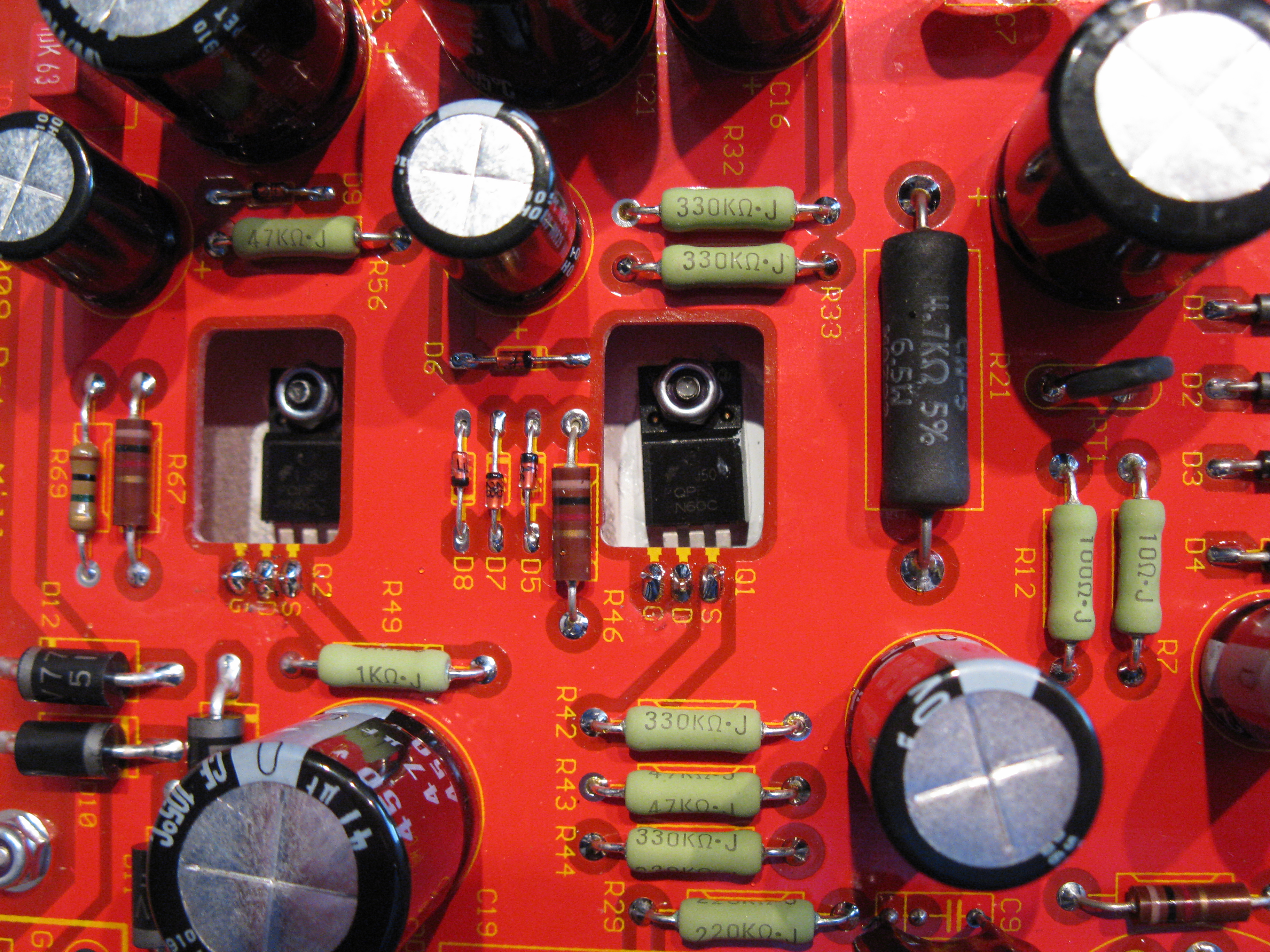
There is local feedback around the output tubes, in the form of plate-to-grid feedback (ala Schade) of about 10%. It's implemented as resistors from the plates of the output tubes to the plates of the driver tubes (the 220k resistors R29 and R47 above). This linearizes the output stage and provides a reasonably low output impedance of about 2.8 ohms (without loop feedback). You see small caps (820pF) from plate to GND to optimize square-wave response in the feedback path.
This circuit employs a considerable amount of distortion cancellation between the driver and output. Though some people will tell you that stage-to-stage distortion cancellation in a push-pull amp does not work, I can assure you it does. (Hint: think of this as two separate, identical single-ended amps that just happen to be joined at the hip). I selected the driver tube type experimentally to optimize the cancellation, winding up with a cheap IF amp pentode that - by itself - is not particularly linear. The most surprising thing to me was how well the cancellation holds over varying load impedances - I suppose the plate-to-grid local feedback helps out there. Anyway, at low power levels (~1 watt) the THD (with no loop feedback) is reduced by almost half compared to what I got using a very linear driver tube.
The power supply
The power supply uses silicon rectifiers and a MOSFET ripple filter for the B+ - no expensive and heavy chokes here. The screen voltage of ~150V is generated from the raw HV supply with a simple MOSFET regulator. These circuits are minimalist designs - no fancy triple-cascoded regulators because, frankly, I do not believe they're needed here.
The C- supply of about -60V is generated from taps off the B+ winding, and is filtered by an RCRC filter with no regulation.
The power transformer was specially designed and built for this amp by Edcor. It has a secondary that has two taps to provide both the raw HV of about 360VDC and a negative supply of -60V that's used for output tube bias and a return for the driver CCS. The nice thing about Edcor power supply transformers - in addition to their very reasonable prices - is that once they design a power transformer it becomes a standard product, so other people (like you!) can go buy one - just order an XPWR139.
The power transformer has a split input primary so can be set up for 120V or 240V operation. I connected the primary to an inexpensive AC entry module that integrates fuses, the power switch, and a voltage selector. This way you do not have to do a lot of AC power wiring. The wiring for this is a little tricky, though, and if you do it wrong you may get smoke and flames - so here's a close-up photo of it:
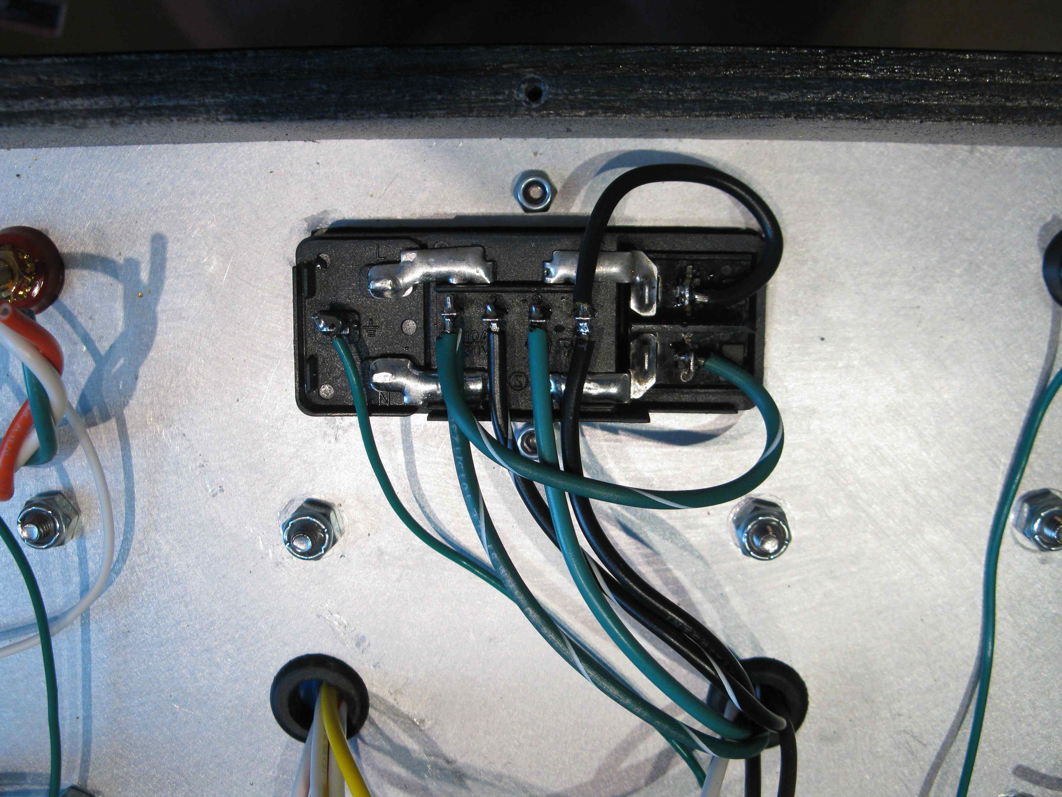
I isolated the AC safety ground, which is connected to the AC plug ground and the chassis, from signal ground using a "ground breaker" circuit. This is an arrangement of series / anti-parallel diodes that presents a high impedance unless there is a voltage of more than two diode drops (about 1.4V) across them. These diodes are large - they must be sized such that enough current can flow through them to cause the fuses to blow if there were to be a short between signal ground and the AC line.
Construction
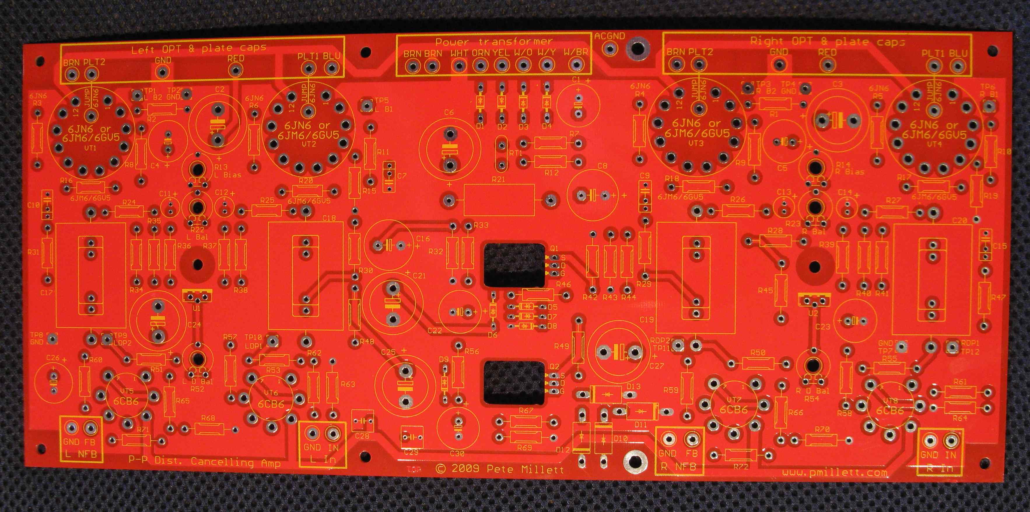
I wanted to make this amp a viable project for a relatively inexperienced hobbyist. To me, that means use of a PCB. A gigantic big bad red PCB!
 .
.
[Shameless self promotion] I've decided to sell PCBs for this project, instead of just throwing it out there for somebody else to pick up. I figured it would be nice to make this hobby self-sustaining. If you're interested in a PCB, click here to see my listings (seller "pmillett"). [End shameless self-promotion]
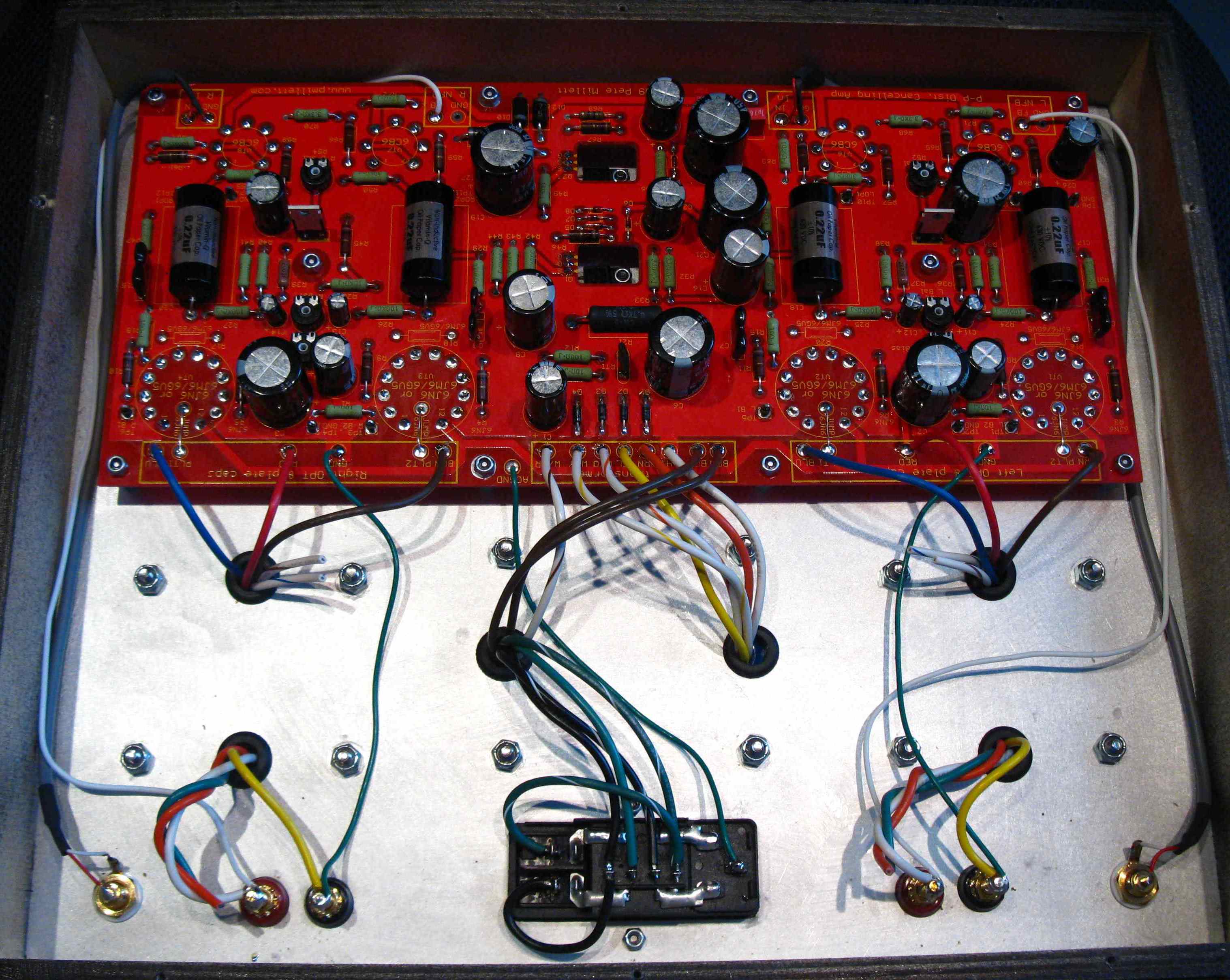
The PC board holds all the components, including the tube sockets. Tube sockets are mounted on the back of the PCB so that they can stick through holes in the chassis, while all the other parts are mounted inside pointing down. The PCB is 13" long by 5.75" wide.
Note that there are some assembly differences depending on if you are using 6JN6 tubes (no plate caps) or 6JM6/6GV5 tubes (with plate caps). For 6JN6 tubes, install grid stopper resistors R3, R4, R5, and R6; for 6JM6/5GV5, install R16. R17, R18, and R20 instead. These resistor options are also noted on the BOM. Also, for 6JN6, you need to install a jumper wire between the PLTx pad and a pad near the center of the power tube sockets. For 6JM6/6GV5, you connect ,a wire from the PLTx pad to the plate cap. You can see all this in the photo below, which shows the amp wired for 6JN6 (click on the picture to see the high-res version).
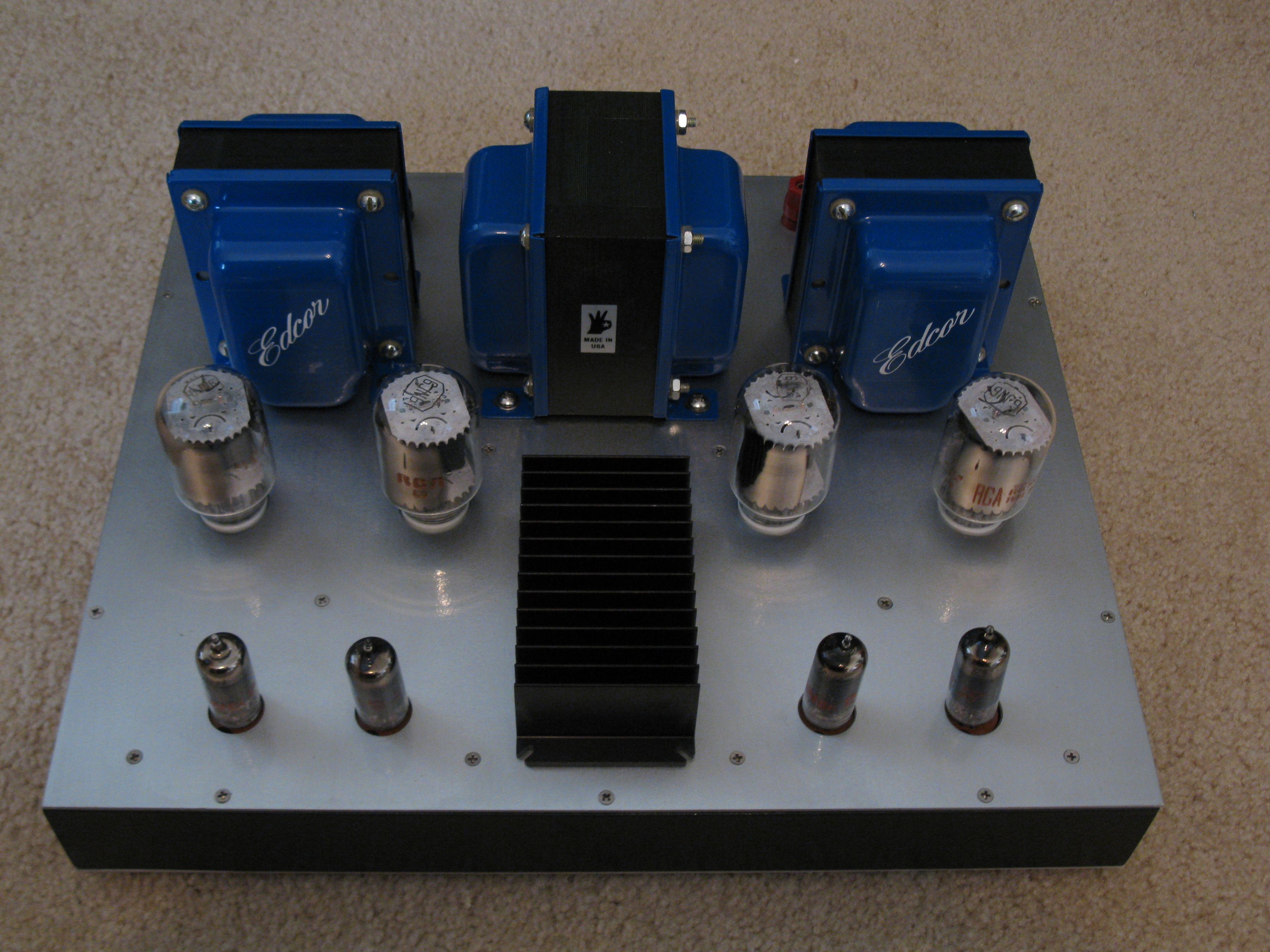
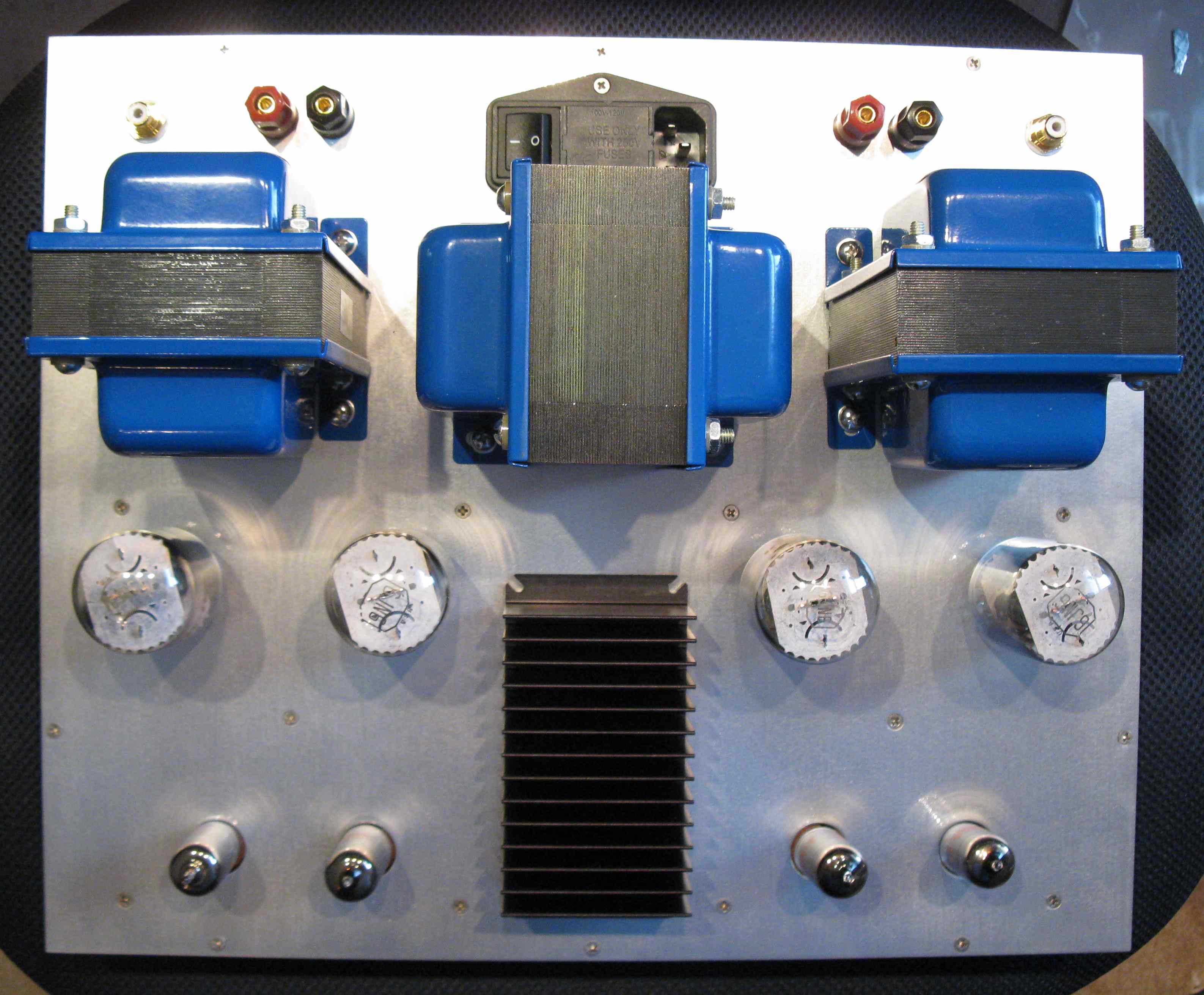
On top of the chassis, the transformers are mounted, as is the AC inlet and input and output jacks. I did it this way so that you can build a simple, inexpensive chassis using flat sheets of aluminum and a simple wood frame. For the panels I ordered cut-to-size 0.08" thick 5053 aluminum sheet from Online Metals. The wooden frame I made from scraps of 1/2" birch plywood I had laying about from a previous guitar amp project. You could also use the small "craft wood" that you can find at places like Lowe's and Home Depot. I glued it together (with simple butt joints) and painted it with a spray can of black Hammerite.
You can download mechanical drawings in a couple different formats. Here is an AutoCAD R12 DXF file of the amplifier mechanics, or a scaled PDF file (scale is 0.75x) showing it. Also, here's a PDF file of just the chassis plate scaled to print on 4 sheets of regular letter paper at 1x scale. You can use this to fabricate the chassis - just tape/glue the sheets to the metal and drill away.
And here is a front panel express FPD file. Beware, I am not 100% sure that it is all correct!
You can, of course, use a conventional aluminum chassis, or another enclosure.
You probably noticed the black heatsink on top of the amp. Originally I planned on just using the chassis plate to heatsink the two power MOSFET transistors in the power supply. It worked OK but the top of the chassis got a little warm. So, I added a heatsink to the top. It mounts using the same holes as the MOSFETs, with a screw going through the heatsink, chassis plate, and MOSFET and a nut on the back. Here's what that looks like from the inside...
To make this work out I had to extend the MOSFET leads a bit. I soldered short pieces of wire to the leads and put some heat shrink tubing around them just in case...
Use silicone thermal compound between the MOSFET and the chassis plate, and also between the chassis plate and the heatsink. Any heatsink will do, or if you don't mind a hot amp you probably don't need a heatsink at all. Even a couple of stick-on BGA heatsinks would work.
Adjustments
There are three adjustment pots for each channel that you need to set up.
Start with both "bias" pots fully counterclockwise (as viewed from inside the chassis) - that sets minimum output stage plate current. The other two pots can be left alone, or centered (they normally come from the factory that way).
The easiest way to set the bias is with two meters (any DMM will work), but you can use one and alternate between test points. You'll find three test points near the power tubes for each channel, labeled LB1, LB2, and GND (left channel) and RB1, RB2, and GND (right channel). The voltage between the xBx test point and ground is an indication of the plate (actually cathode) current through each output tube. The current is sensed across a 10 ohm resistor, so 1mA of current will read 10mV on a DMM.
The target cathode current is 40mA for all four tubes. That means 400mV, or 0.4V, on all four of the test points.
After you power the amp up (the first time it's a great idea to do this with a variac, so you can stop if you smell smoke) and verify that the plate voltage is OK (around 325V) and the screen voltage is OK (around 145V), move the bias control up (clockwise) so you are measuring around 400mV on the test points. The balance pots will change the ratio of current between the two tubes, so moving it can make the voltage equal on the xB1 and xB2 test points.
Don't worry about accuracy yet. Let things warm up for a good 10-15 minutes.
Once the amp is warmed up, go back and twiddle the bias and balance pots so you have 400mV on all four test points. You will have to go back and forth as there is some interaction between channels. You want the currents on a given channel to match closely (within a few mV is best), as this balance has a big affect on low-frequency distortion.
Once the outputs are set, you can adjust the driver balance. There are two ways to do this:
If you have access to a distortion measurement or FFT (like a soundcard), set the driver balance for the lowest distortion at about 1 watt output.
If you don't have a way to measure distortion, you can set the pot so that the voltage on the xDP1 and xDP2 test points for a given channel are equal (it doesn't mater if the two channels are different). Or, if you have superhero hearing, set it by ear.
If you cannot achieve balance in either the output or driver tubes, try swapping tubes around, or try different tubes. These tubes are cheap, so you can afford to buy extras...
It is wise to repeat the bias adjustments periodically as the tubes age. You'll also want to repeat it if you change tubes.
Measurements
I set up and made measurements of the amp with and without the 6dB of global feedback. Here is a summary:
| Without loop feedback | With 6dB loop feedback | |||
| 1 watt out (2.82V RMS into 8 ohms) | 0.17% THD | 0.21V RMS in | 0.09% THD | 0.40V RMS in |
| 5 watts out (6.32V RMS into 8 ohms) | 0.71% THD | 0.40% THD | ||
| 10 watts out (8.9V RMS into 8 ohms) | 2.26% THD | 1.27% THD | ||
| At clipping (5% THD) | 17.8W (12V RMS) | 0.98V RMS in | 17.8W (12V RMS) | 1.93V RMS in |
| Zout | 2.81 ohms | 2.31 ohms | ||
Note that to a large extent, the frequency response and THD vs. frequency performance are dictated by the output transformers. I used Edcor transformers here (CXPP25-MS-8K), which are affordable and measure pretty well. I also tested using some expensive "imported" iron; the THD at high frequencies was considerably better (nearly flat to above 20kHz) and the HF response extended slightly.
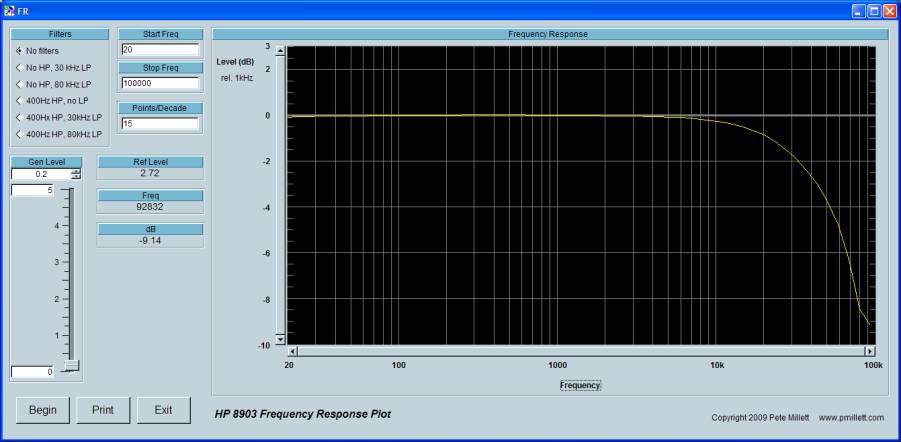
And a bunch of plots... first set without feedback:
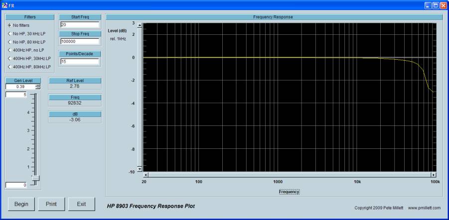
Frequency response @ 1W into 8 ohms :
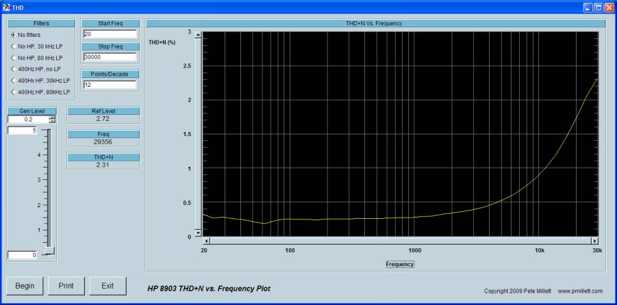
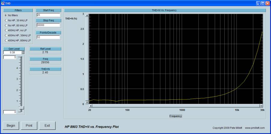
THD+N vs. frequency @ 1W into 8 ohms (note no filters used so some 60Hz noise shows up)
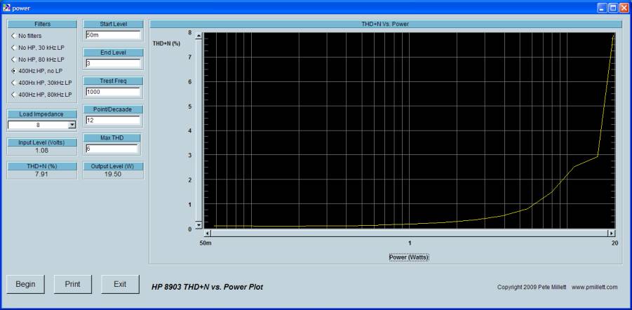
THD+N vs. output power (into 8 ohms):

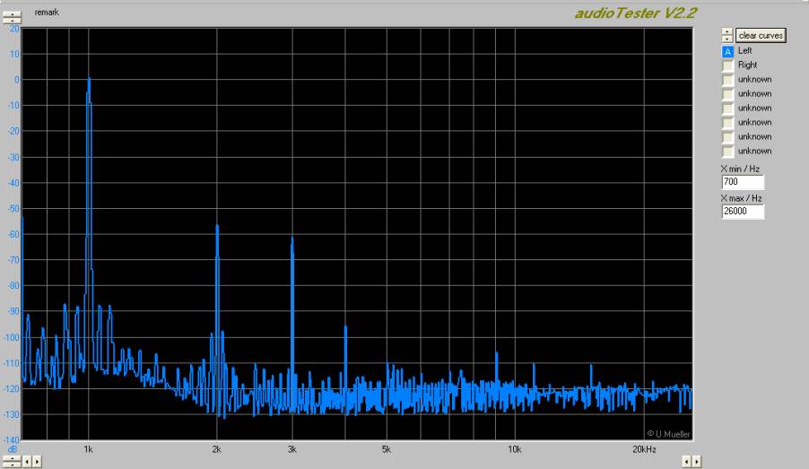
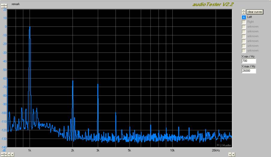
FFT @ 1kHz, 1W into 8 ohms:
Square wave response - 20V P-P @ 1kHz into 8 ohms...
...and ~10V P-P at 10kHz into 8 ohms:
Now plots with 6dB of loop feedback... about what you would expect: lower THD and noise, flatter FR, but a few higher harmonics and a little funkiness on HF square waves...
Frequency response @ 1W into 8 ohms :
THD+N vs. frequency @ 1W into 8 ohms (note no filters used so some 60Hz noise shows up)
THD+N vs. output power (into 8 ohms):
FFT @ 1kHz, 1W into 8 ohms:
Square wave response - 20V P-P @ 1kHz into 8 ohms...
...and ~6V P-P at 10kHz into 8 ohms (sorry, different level than the other plot):
How does it sound?
I hate that question. After all, I am an engineer...
Well, I like it. I like it a lot.
It possesses none of the syrupy smoothness that the 300B amp had. It is tight sounding - wonderful bass response (as the measurements would suggest). I think I prefer it with the loop feedback, though honestly there is not much difference to my ears with or without the feedback.
Those accustomed to SET amps might find the sound a little edgy, especially if you're using horn speakers. But it's moderate damping factor seems to take some of the edge off, and it plays well with all of the speakers I've tried, including Jordan MLTQWPs, Fostex FE167s, and Klipsch Heresys. With 18W the Heresys will drive you from the room...
Above all, for a tube amp, this amp is accurate. The measurements confirm it.