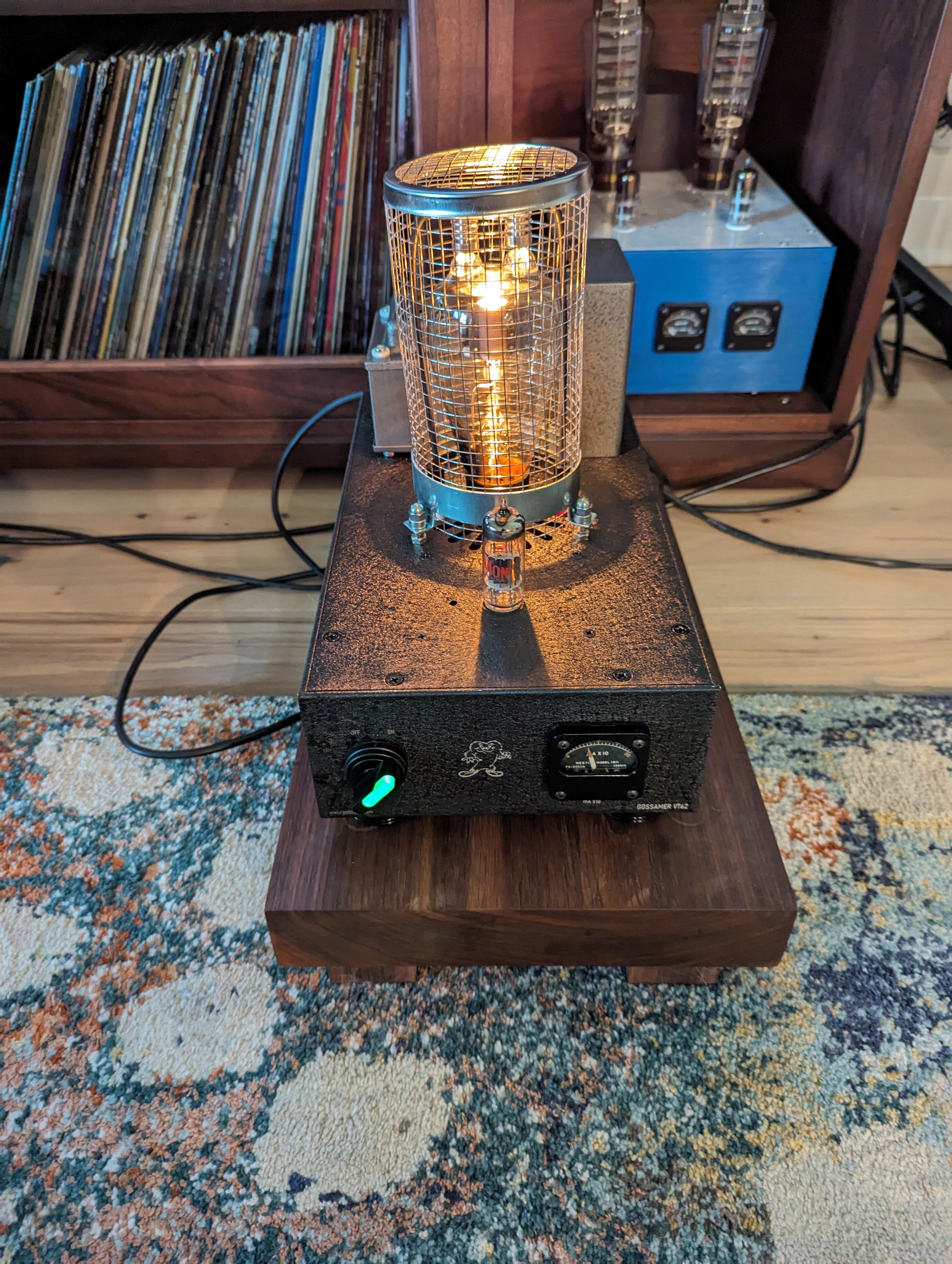
"Gossamer" - VT-62 (RAF) / DET12 / 4304CB / 834 SE A2 amplifier
The story of this amp started at ETF, where a pair of RAF VT-62 tubes were up in the auction. Nobody bit, so I bought them for a reasonable price. Fast forward several years later...
The VT-62 is a thoriated tungsten 50 watt triode intended for RF application. It, and its near exact equivalents including the 4304CB and DET-12, as well as UX4-based 834, have been used in a few audio amp designs. You can see some info on this tube and its relatives at the Valve Museum. Datasheets for some can be found online: 4304, RCA 834. These are rare - and expensive - tubes. I'm fortunate that I happened on a few at reasonable prices and have 3 pairs now.
Why "Gossamer"? My friend Dave suggested that the tube looks like the Gossamer character from bugs bunny.
Since this tube is designed for RF amplification, if you want to get significant audio power out of it, you really need to run it in A2, where you drive the grid positive. It turns out that very close to zero bias isn't a bad place to run, with a modest plate voltage of around 500V. That gives you about 100mA of plate current and 50 watts of plate dissipation, which is the limit. At 50W the plate glows a dull red. I am running it a bit more conservatively, around 450-475V and 80mA or so, and a plate load impedance of 5k. At this operating point I get about 15 watts out. If you push to the limits you can approach 20 watts.
To get decent distortion and damping factor, I used a significant amount of NFB. It's loop feedback taken from the output back to the input tube cathode.
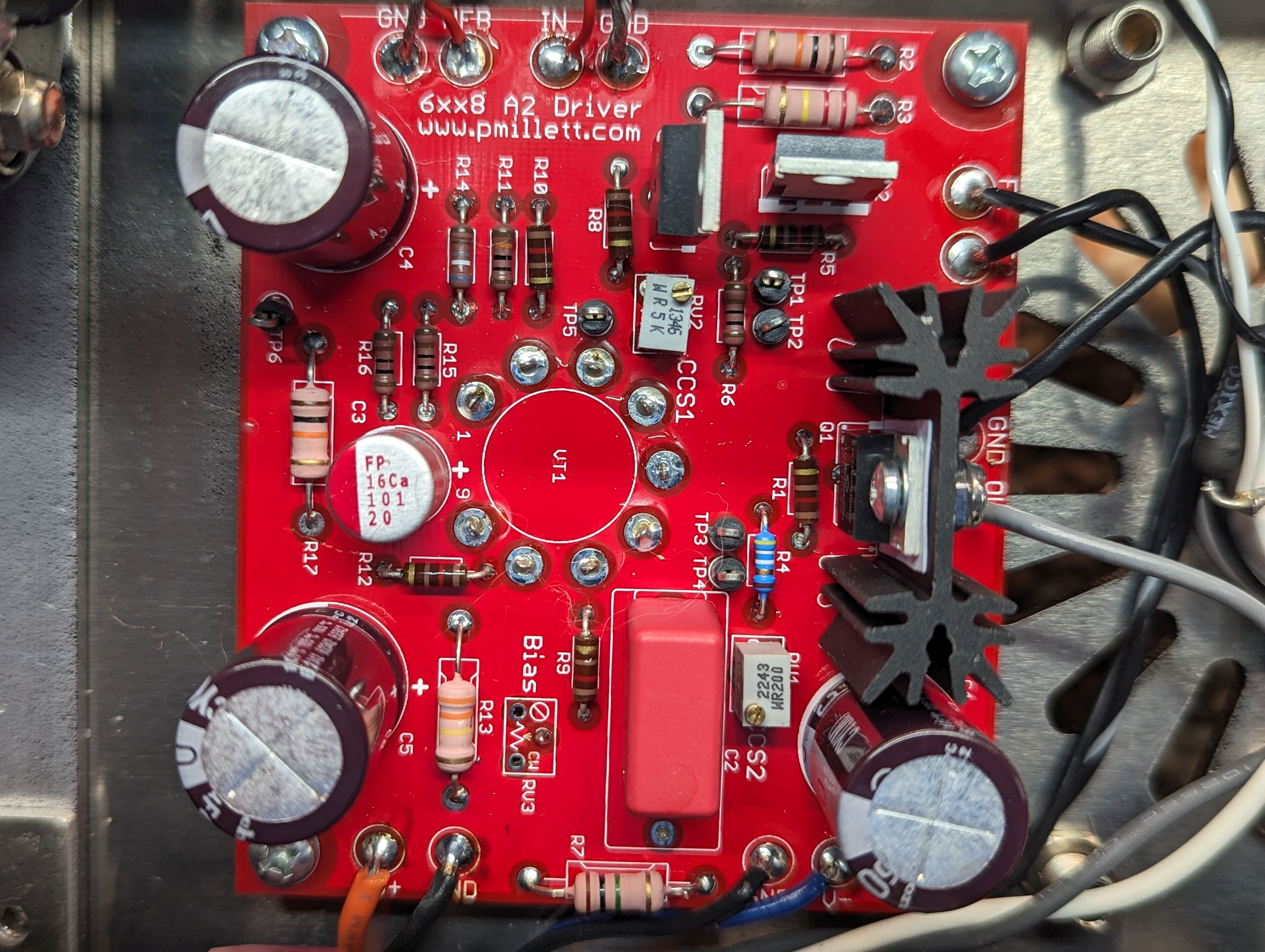
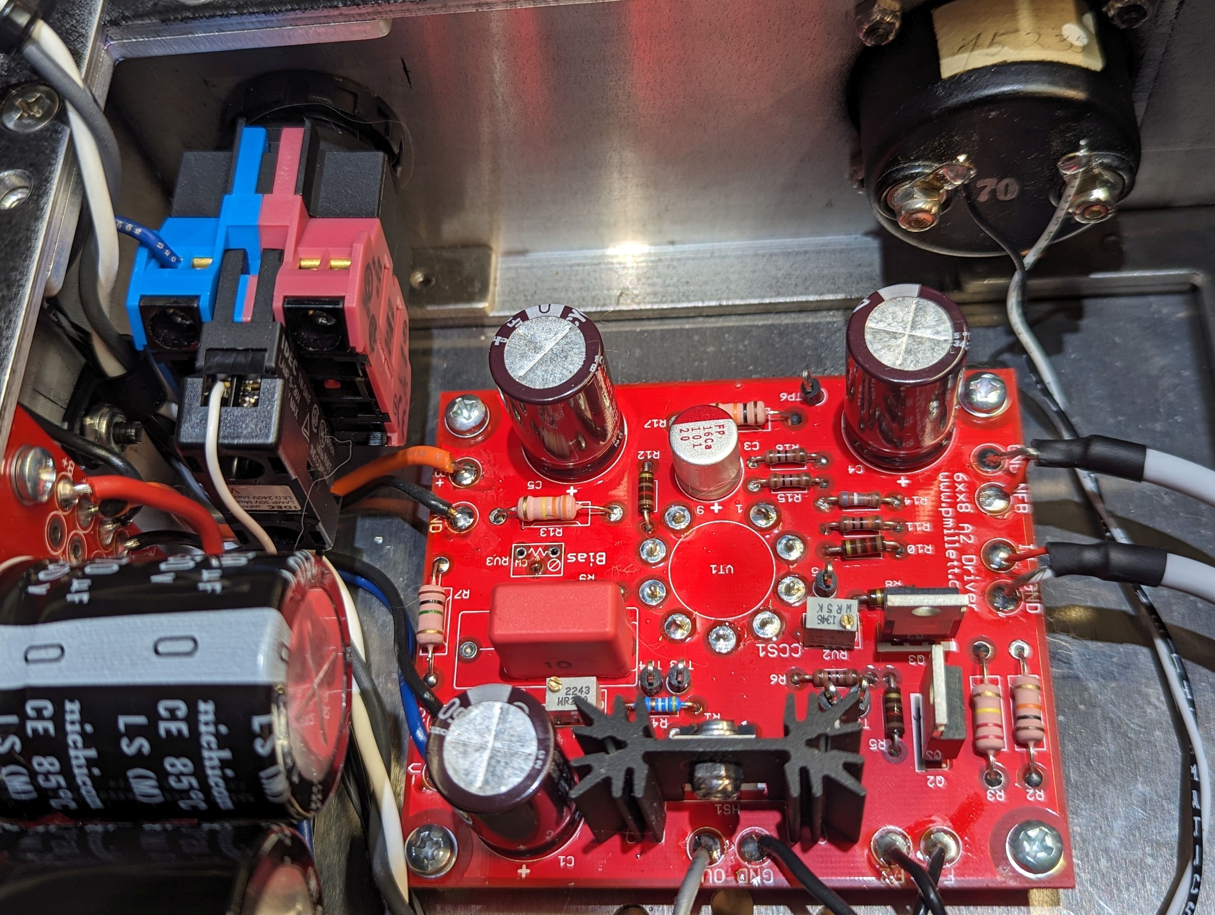
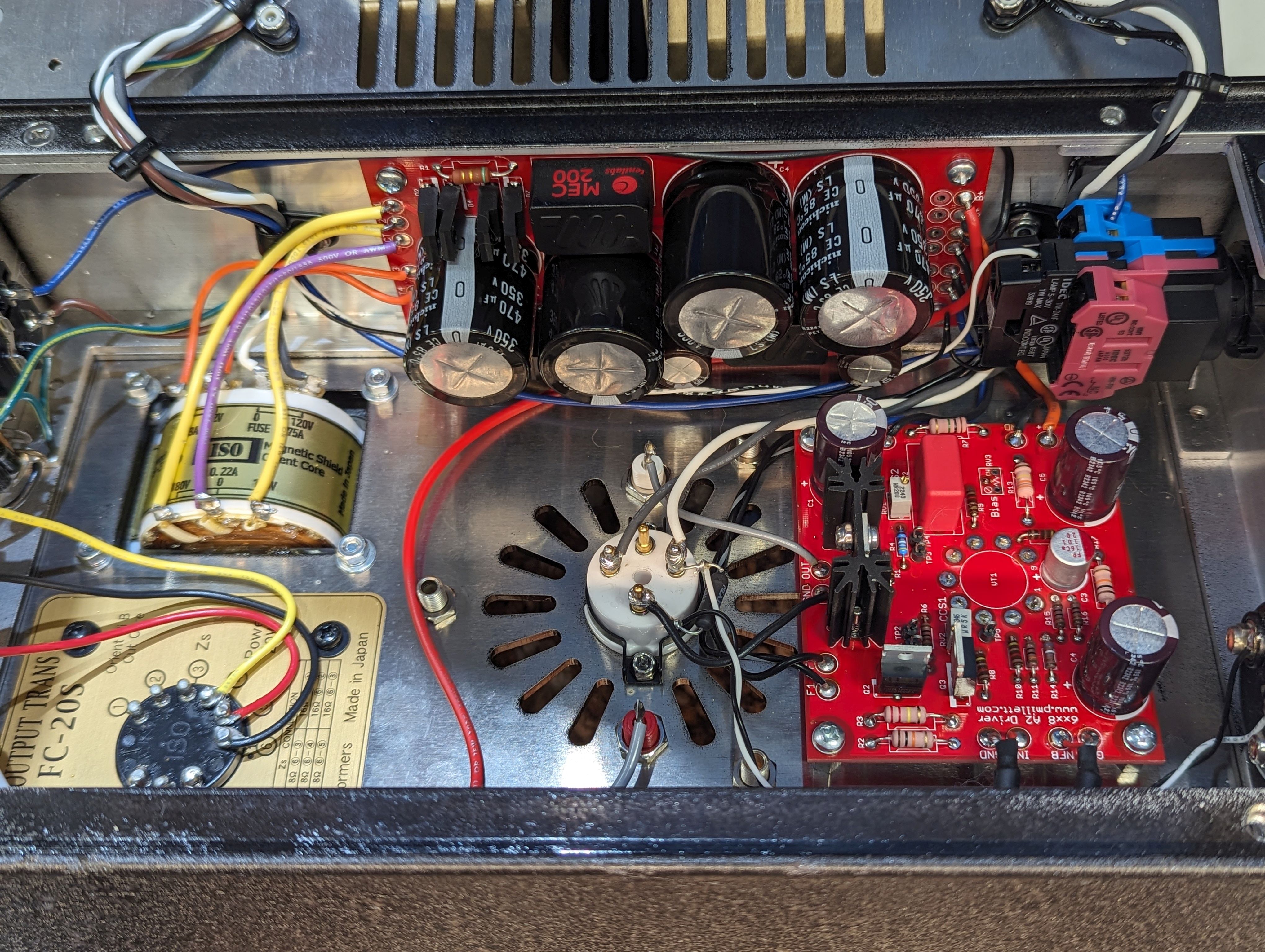
I designed an A2 driver board for this amplifier. It can be seen on it's own web page here. It uses a triode/pentode tube, with the triode as the first stage and the pentode connected as a cathode follower, DC coupled to the VT-62 grid. The triode is 12AX7-like, with a mu of 100. That provides enough gain to get some significant NFB. Basically I used as much NFB as I could and still get full power out at 2V RMS in.
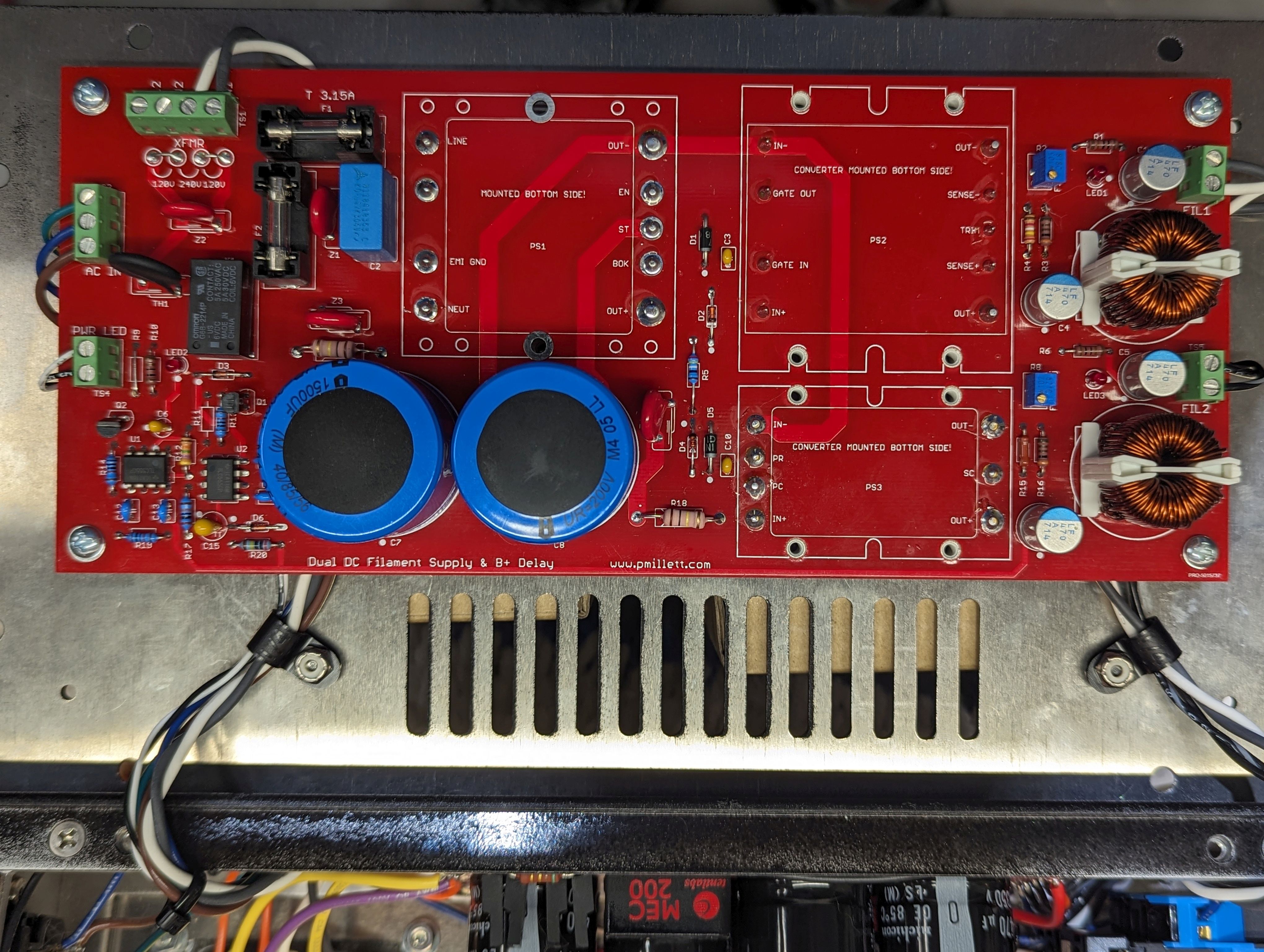
The LV power supplies were implemented using a board that I already had. It uses Vicor DC/DC converters to generate 6.3V for the driver and 7.5V for the VT-62, and also implements a delay to apply the B+. Details here...
The HV supplies (500V B+ and 250V for the driver) is on another PCB that I designed for this project. It uses SiC rectifiers and Tentlabs MEC electronic chokes. Details on the PCB are here...
I will sell the driver and HV power supplies on my eBay store. Not so sure about the LV supply as it's a bit of an oddball...
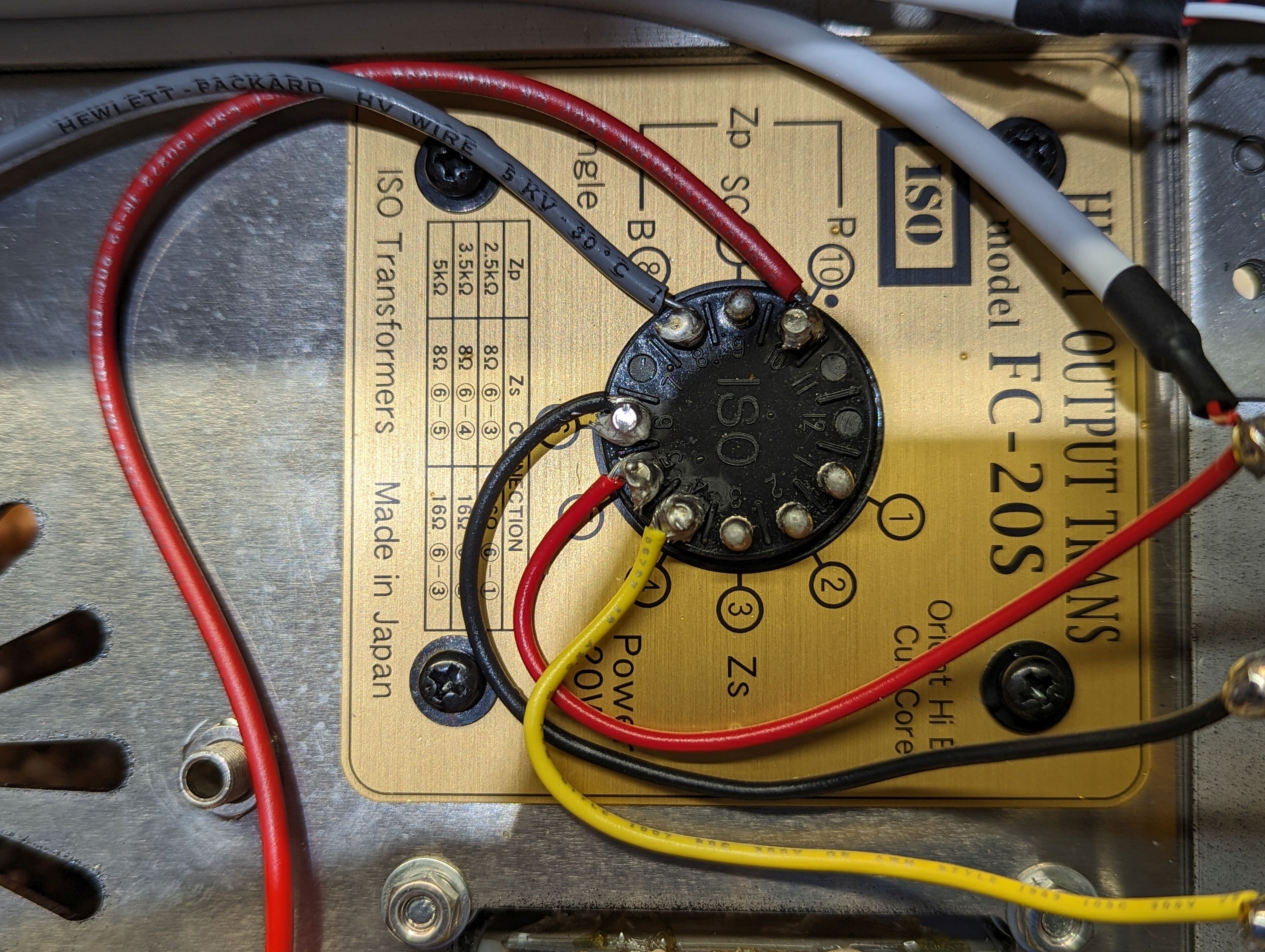
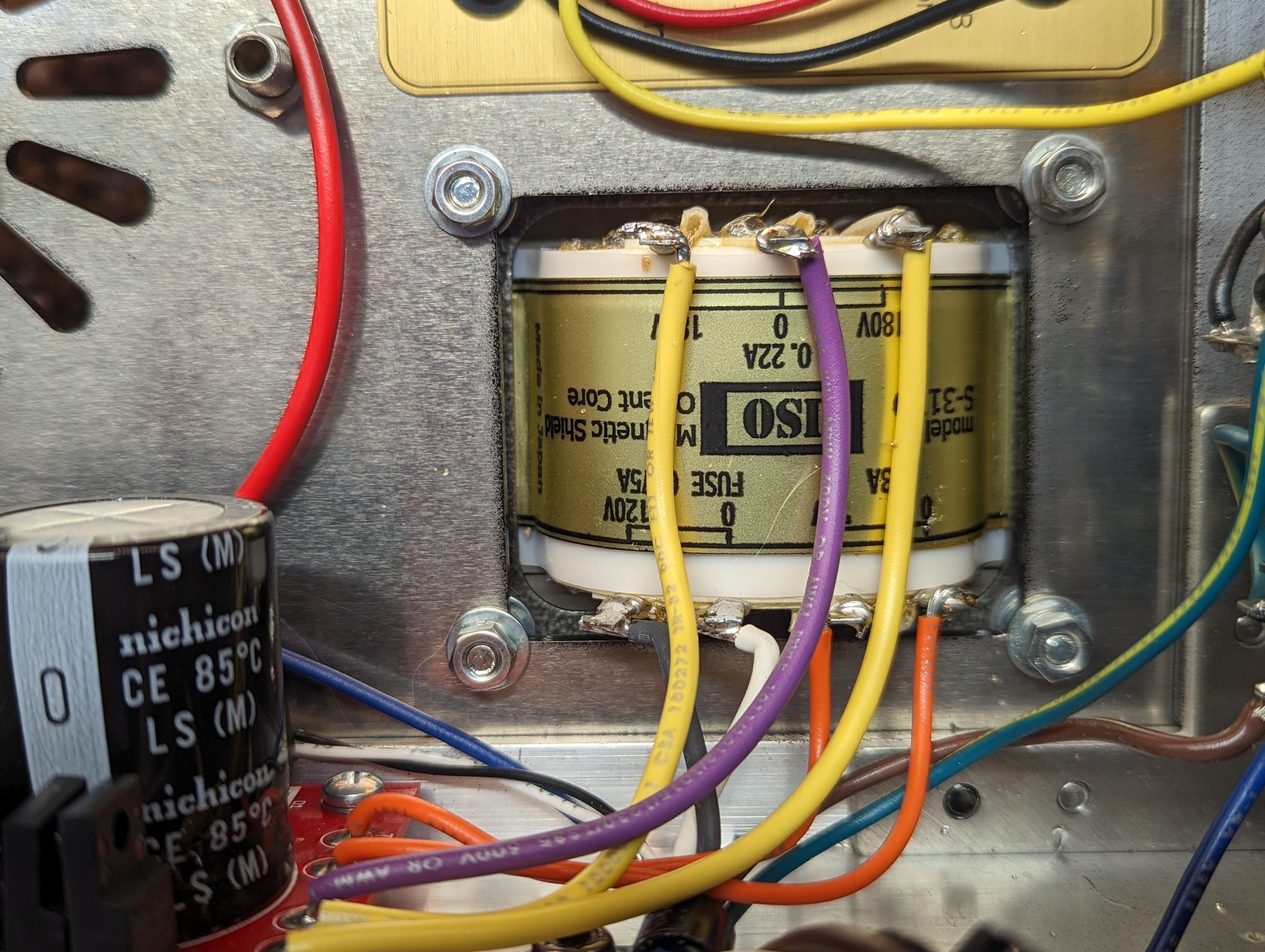
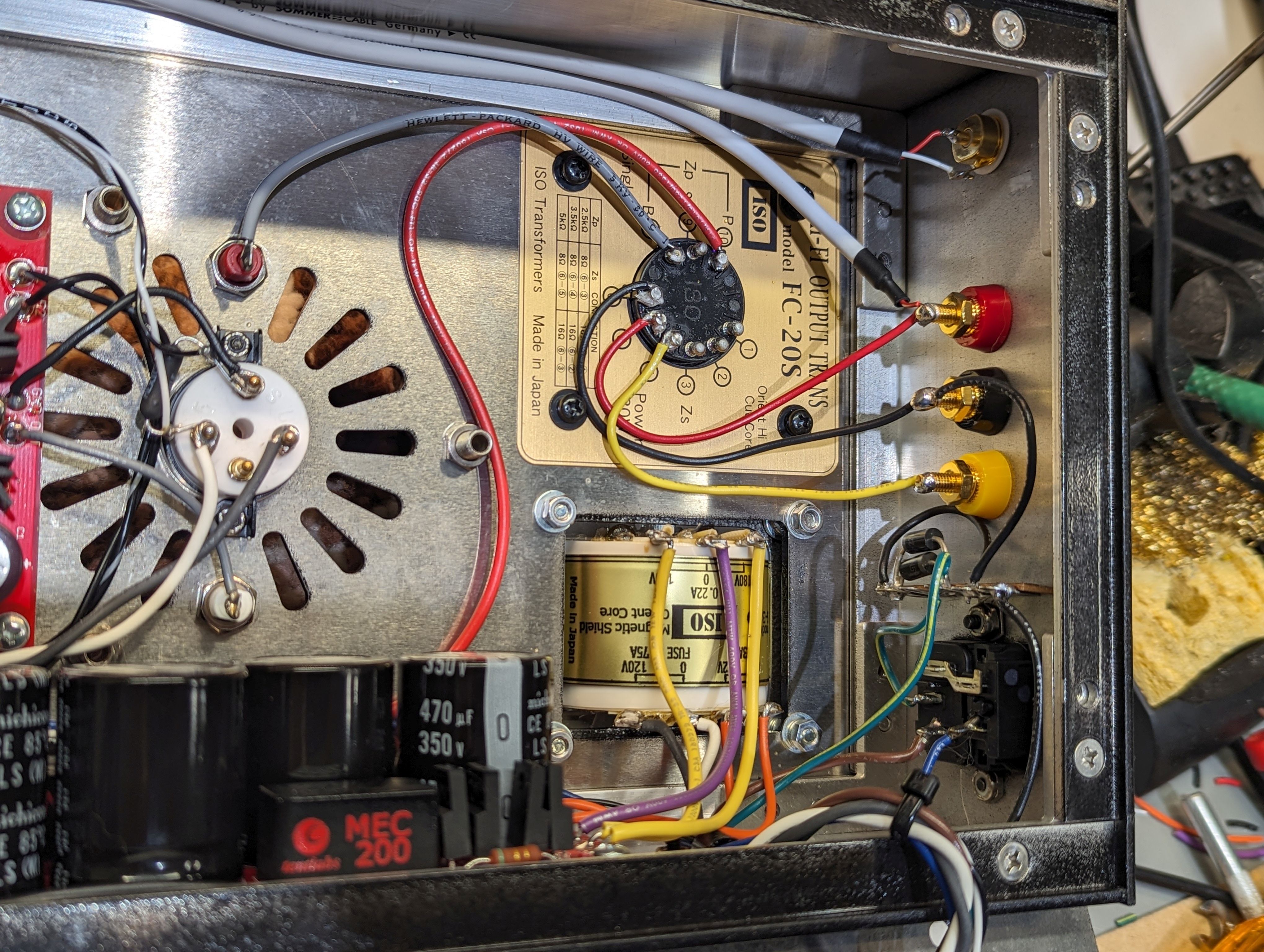
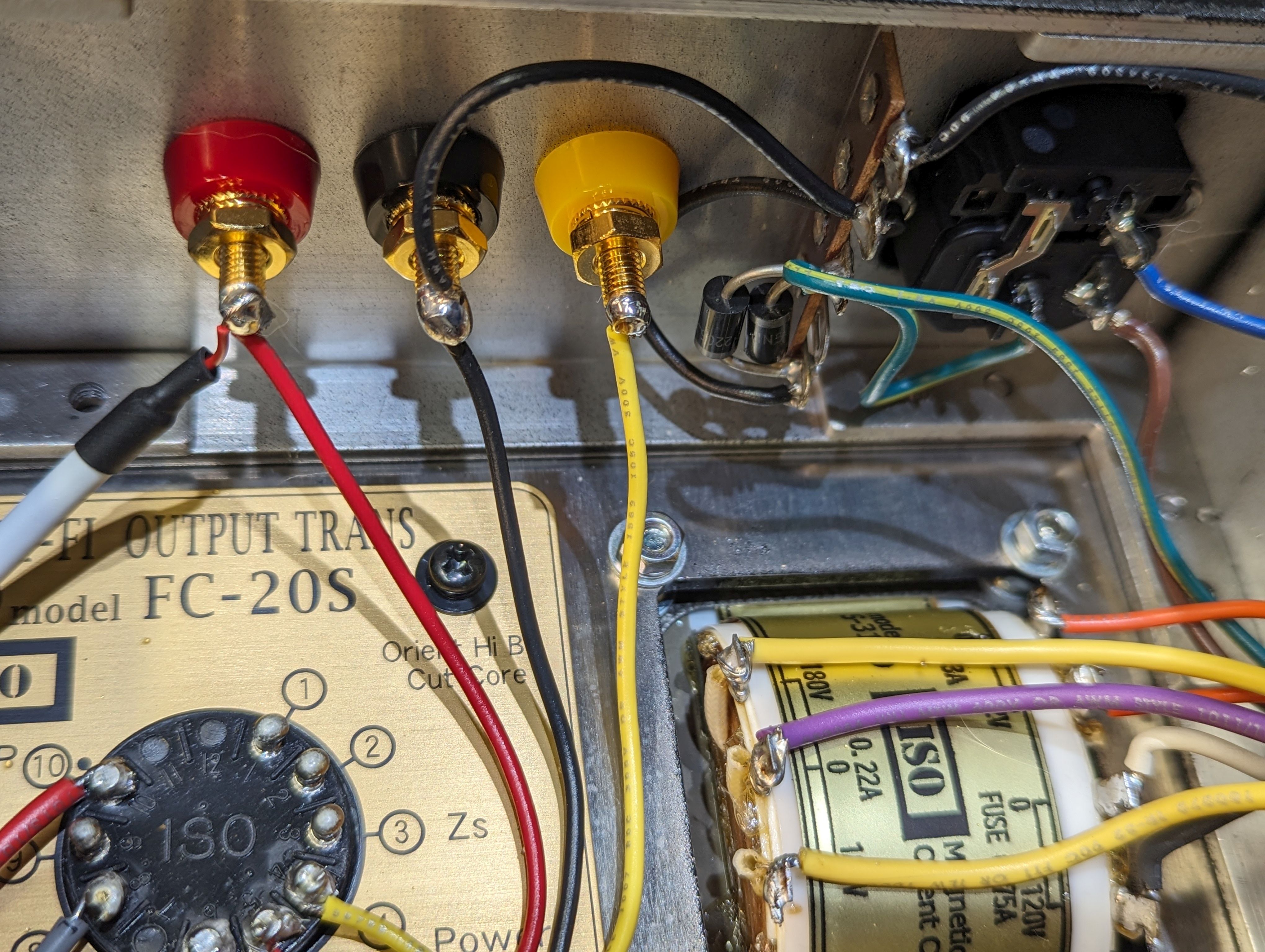
I used an ISO (ex-Tango) FC-20A output transformer, wired as 5k:8. I had ISO wind a custom power transformer for this amp. For ISO iron in the US, contact tubesusa.com. The chassis were made by Landfall Systems. Those tube cages? They are "grilling baskets" I got from Amazon, mounted to big capacitor clamps and banana plugs.
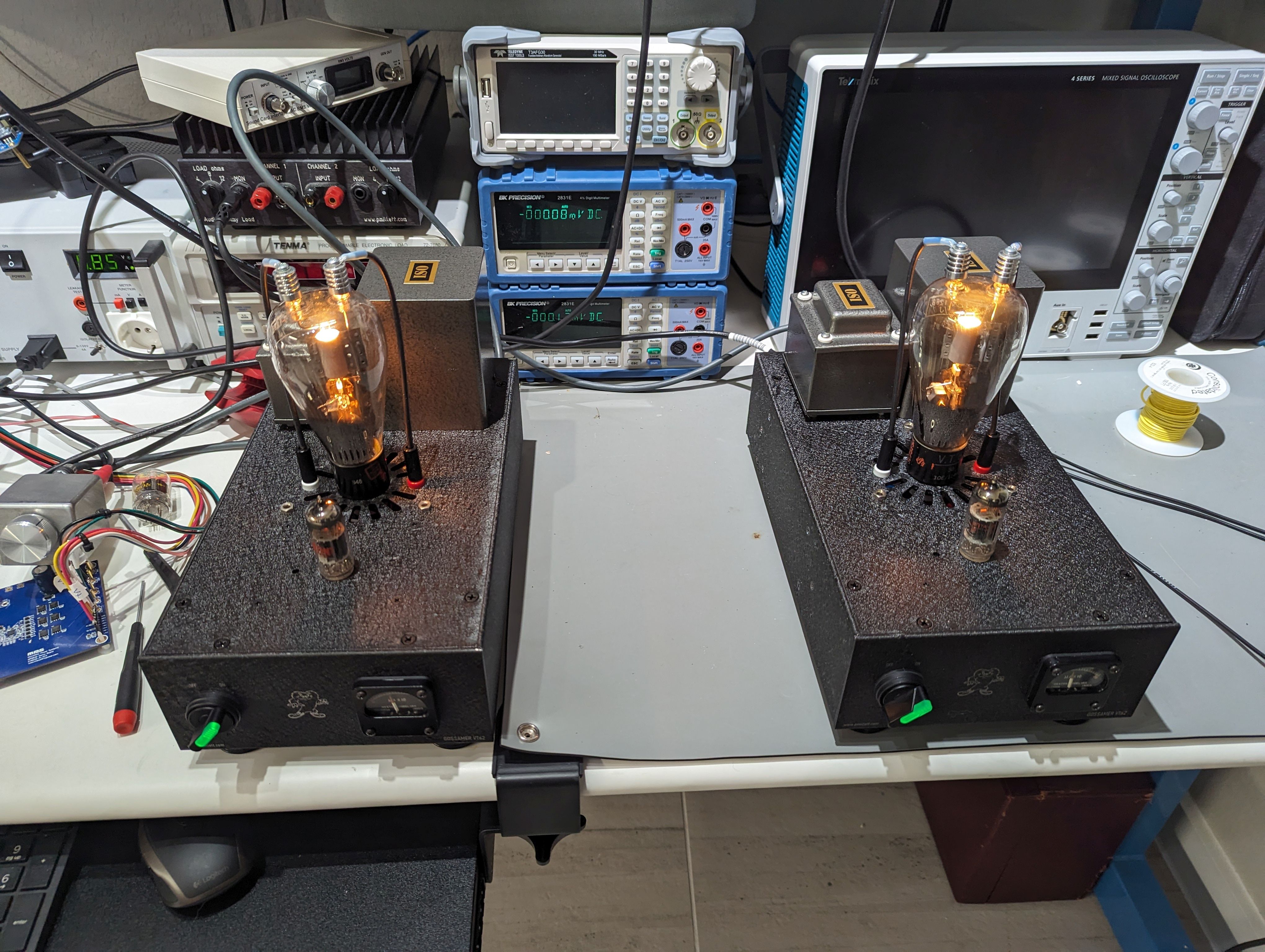
The LV PS is mounted to the bottom of the chassis, So you have to open it like a book with the wiring going across the hinge point.
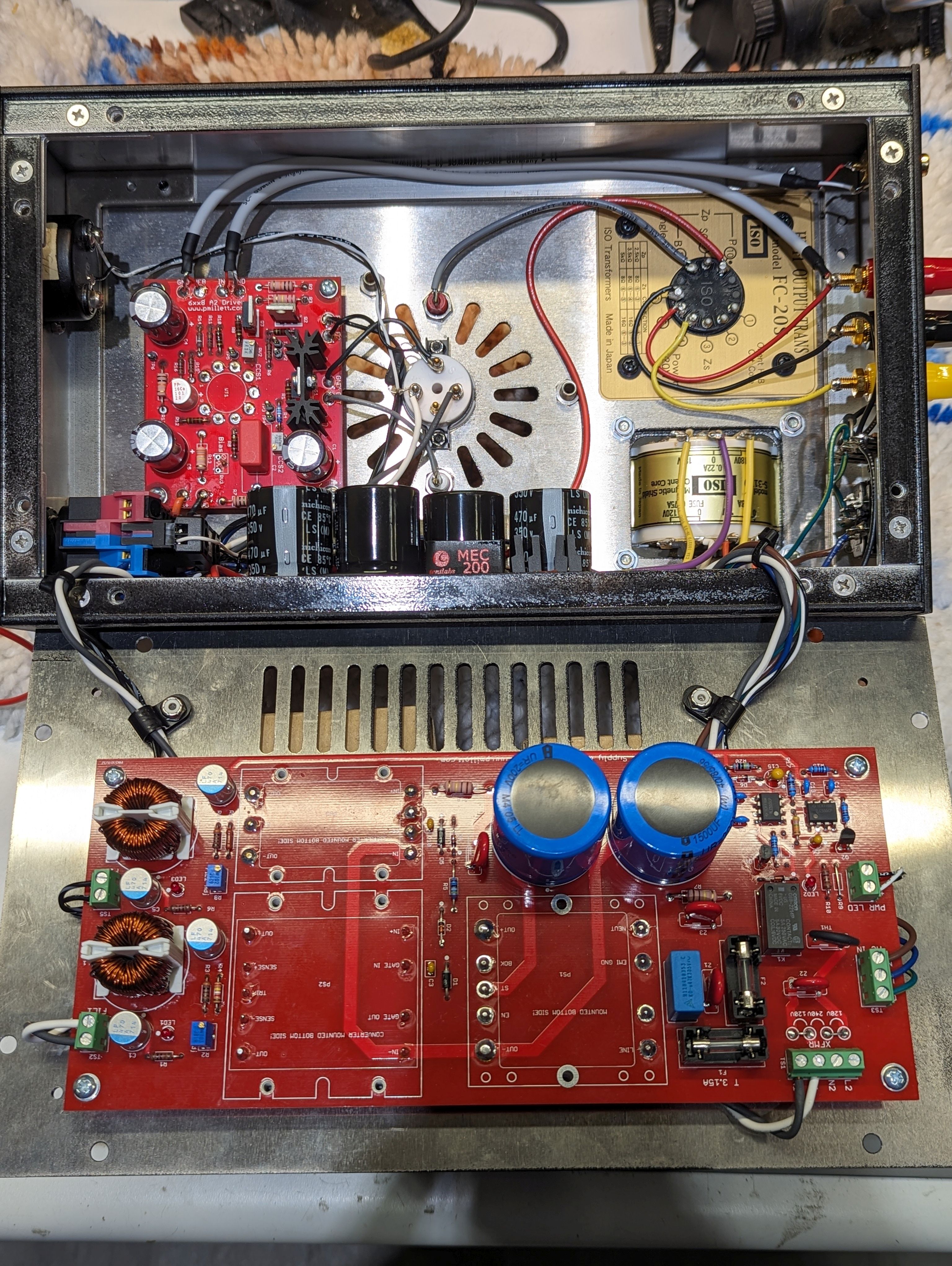
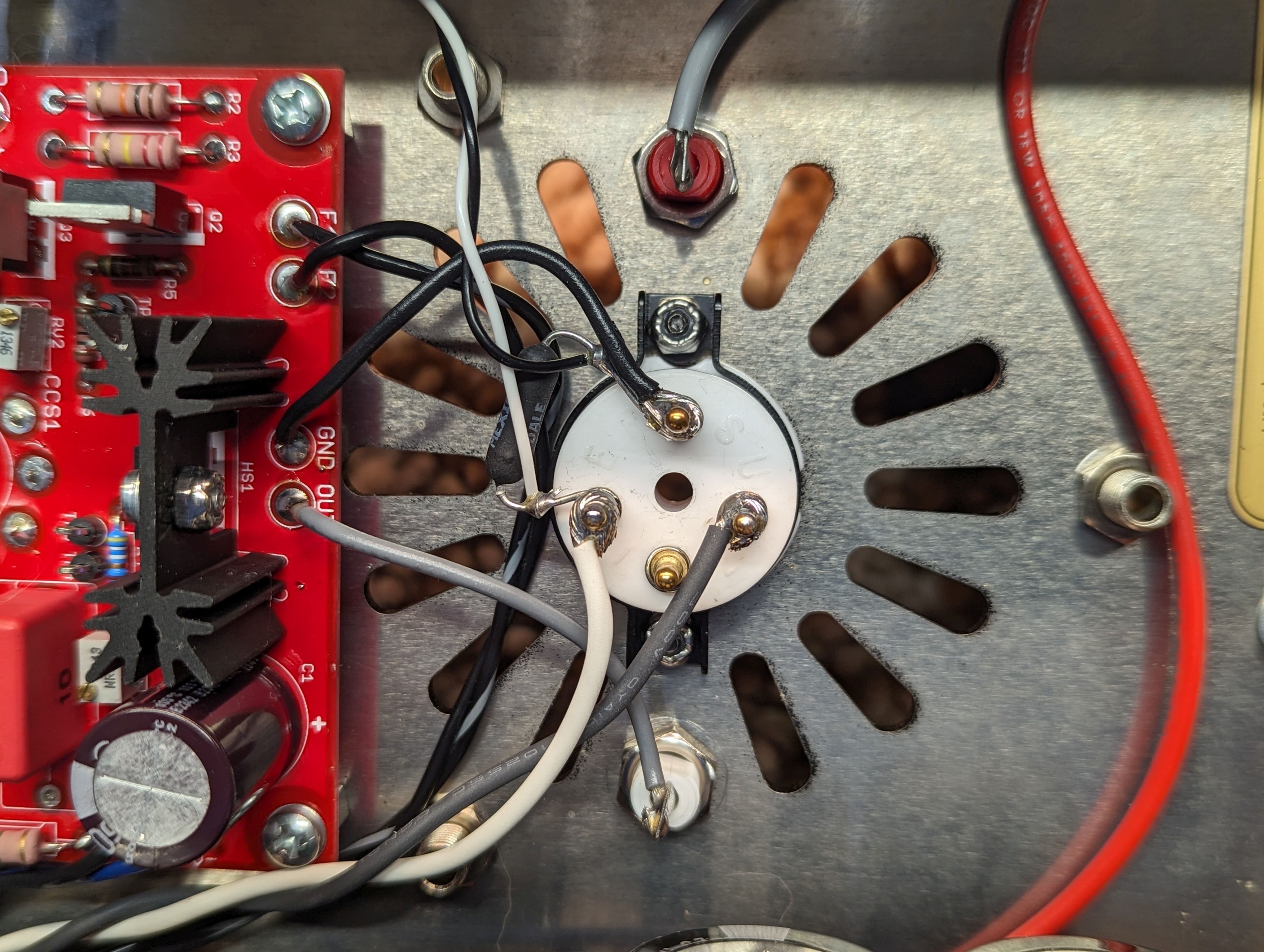
With all the PCBs, the inside of the amp is pretty busy. Here are a bunch of pictures of the guts... most are hyperlinked to bigger photos.
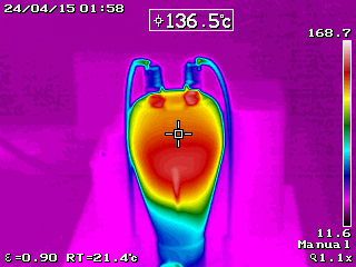
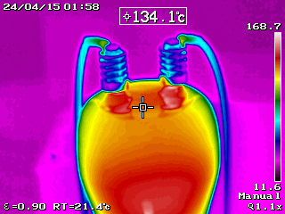
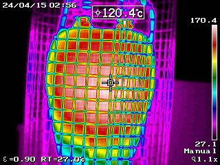
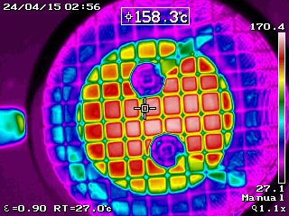
This tube runs HOT... some pretty thermal images:
So, what about performance?
Here is the frequency response:
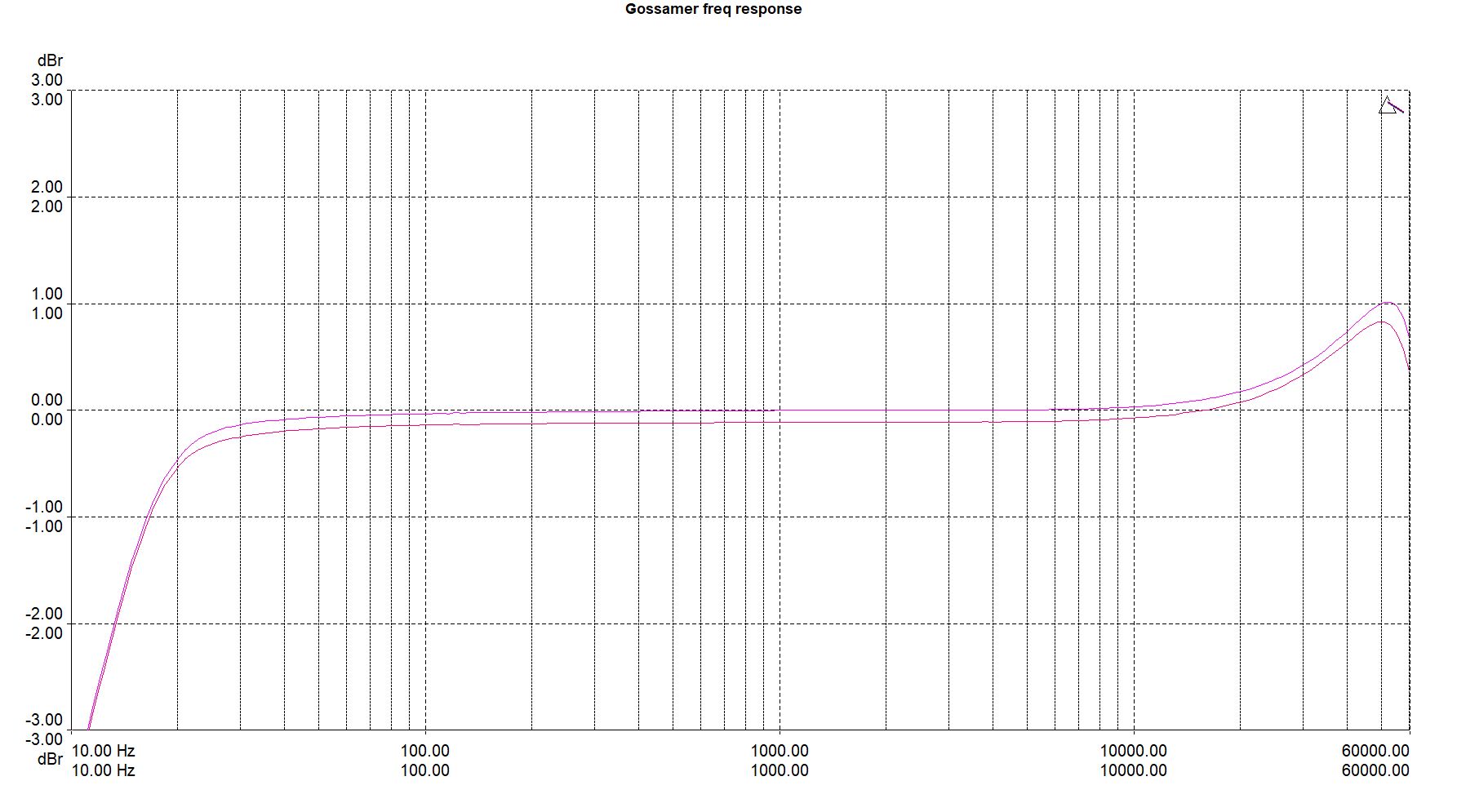
Down 3dB at about 12Hz and around 80kHz. It is a little underdamped with a 1dB bump at 50kHz, but I didn't bother trying to reduce that. The two traces are the two monoblock amps.
THD+N vs. output power:
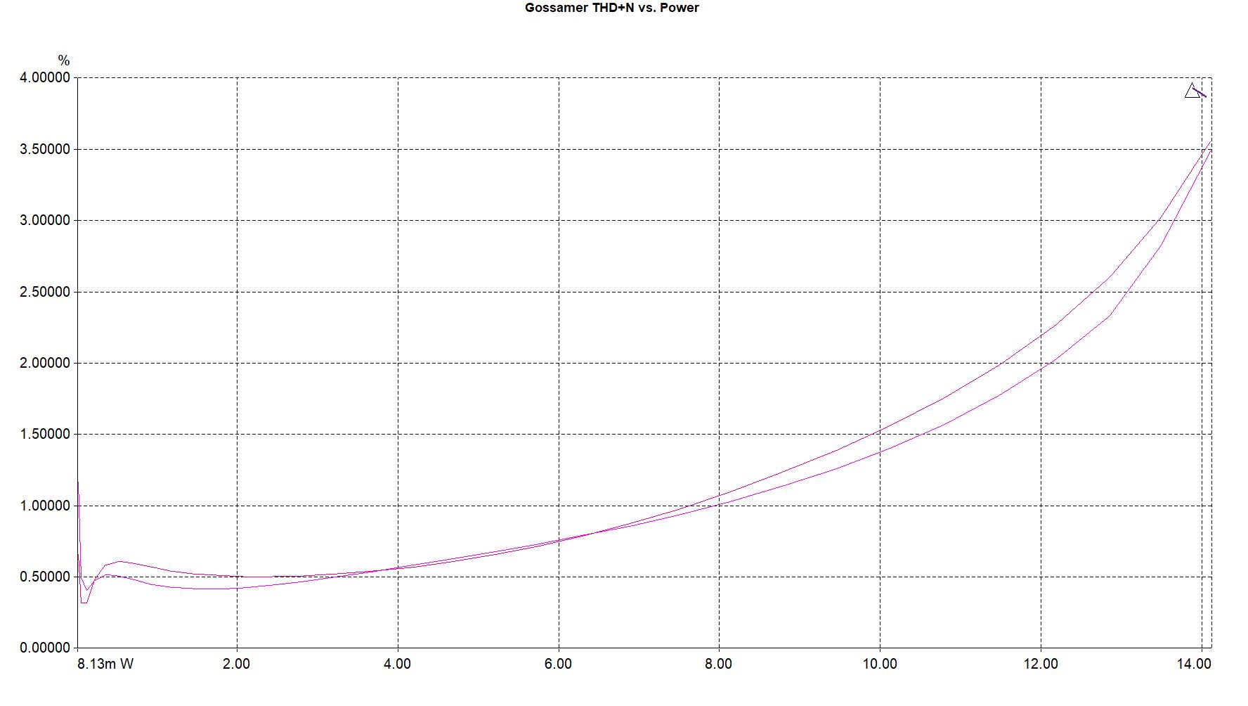
Around 0.5% at 1 watt, 5% where clipping starts at 15-16 watts.
There is a bit of 2nd order cancellation happening here, as an FFT of the output shows the 2nd harmonic as lower than the 3rd (but the driver alone has 2nd dominant). Sorry, I guess I didn't capture the FFT. It does not look like a normal SE amp (think 300B with massive 2nd and 4th) - it almost looks like a push pull amp. And it doesn't sound like a typical SE amp either.