Tube Microphone Preamp
A while back a friend that does some home recording asked me about a tube microphone preamp. Something I hadn't designed yet... so I designed one.
This particular design is pretty high-end. I started with the best microphone input transformer I could find (at least without having something custom made). So this is not an inexpensive preamp... the input transformer alone sells for $135! The total cost for everything including the case and PCB is right around $400.
I'm selling the PCBs for $30 each on eBay.
The Circuit
The circuit topology uses an input transformer, followed by a 6922/6DJ8/ECC88 cascode stage. The output uses another ECC88, in SRPP, with some feedback around it. The feedback has two settings, giving two gain selections.
Click here for a full PDF schematic. You can download the BOM either in PDF or XLS format.
Input is via a Neutrik combo 1/4"/XLR jack. The signal passes through a Lundahl LL7903 transformer. Provisions for phantom power as well as a polarity flip switch is included.
The amp stage proper: Cascode followed by SRPP. I know some people hate SRPP - it's too trendy, I guess. But here is seems to me the best choice, able to drive a 600 ohm load. Note some NFB around the final stage, two different amounts selected by a switch. The output - unbalanced, no output transformer - is supplied via another 1/4"/XLR combo jack. Yes, the XLR is the wrong sex, but you can't get a male combo jack, and front panel space was limited.
The power supply is, uh, unconventional. What? Who? Me? Yup. A switching supply, generating 6.3V filament voltage and +200V B+ from a 48VDC input. The beauty of switching supplies is that the noise they generate - and yes, they do generate some noise - is at high enough frequency that it's easy to filter, and above the audible range. For a low-level preamp like this I'd rather have a few millivolts of 100kHz than a few millivolts of 60Hz!
Here's the input and filament buck:
...and here's the B+ boost:
I powered this from a desktop-type switching 48V 1A power supply.
Performance
Some measurements:
| Parameter | Gain setting | HiZ load | 600 ohm load |
|
Maximum gain 10mV in 1kHz |
Low | 48dB | 46dB |
| High | 58dB | 55dB | |
|
Maximum output voltage 1kHz |
Low | 20V RMS | 9V RMS |
| High | 42V RMS | 9V RMS | |
|
THD+N 10mV in max gain |
Low | 0.6% | 0.65% |
| High | 0.47% | 0.5% | |
|
THD+N 10mV in 1V out 1kHz no LP filter |
Low | 0.25% | 0.25% |
| High | 0.15% | 0.15% | |
|
Freq Response 20Hz - 50kHz 10mV in 1V out |
Low | +/-1.5dB | +/-2dB |
| High | +/-1.5dB | +/-2.5dB |
....and some graphs (all taken with a high-Z load):
Frequency response, low gain setting, 10mV in and 1V out:
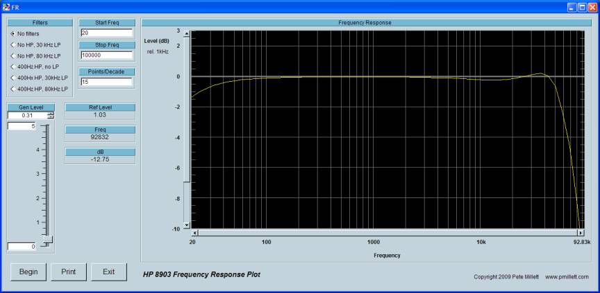
Same at high gain:

...the peaking at HF can be adjusted by changing the RC loading on the transformer secondary.
THD+N vs. output voltage, low gain setting:
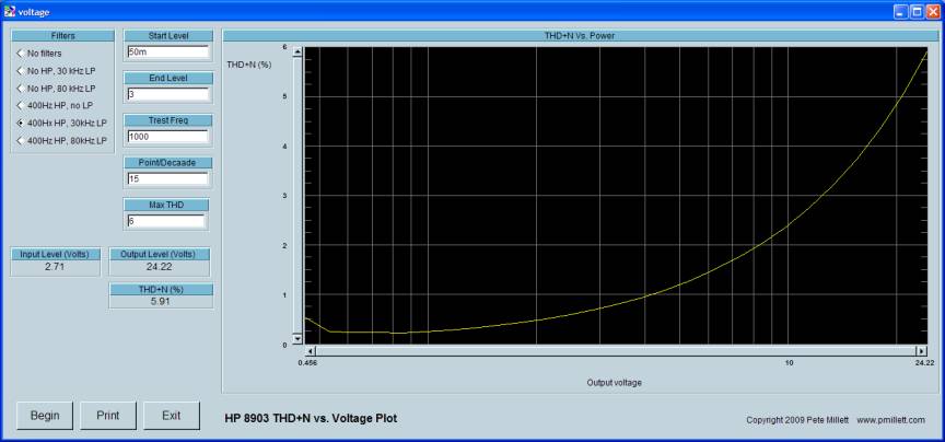
...and high gain:

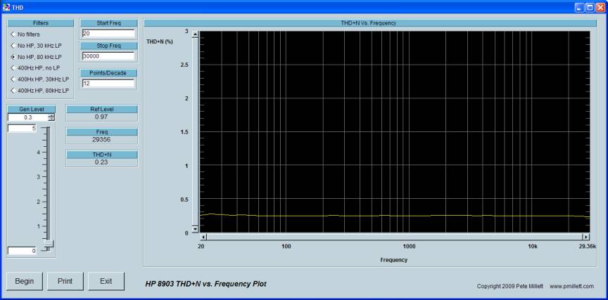
THD+N vs. frequency, 10mV in 1V out, boring:
...and finally an FFT, 10mV in, 1V out:
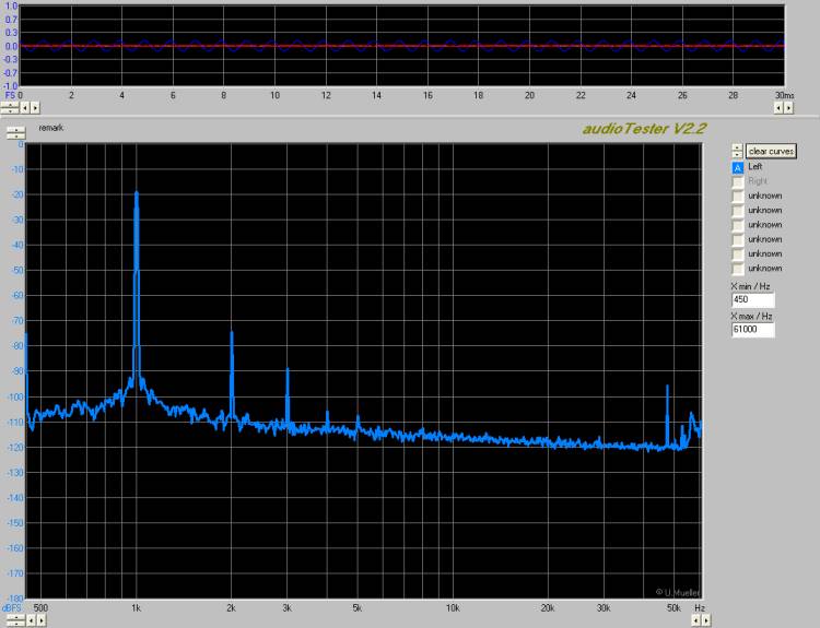
...nicely tubey!
Implementation
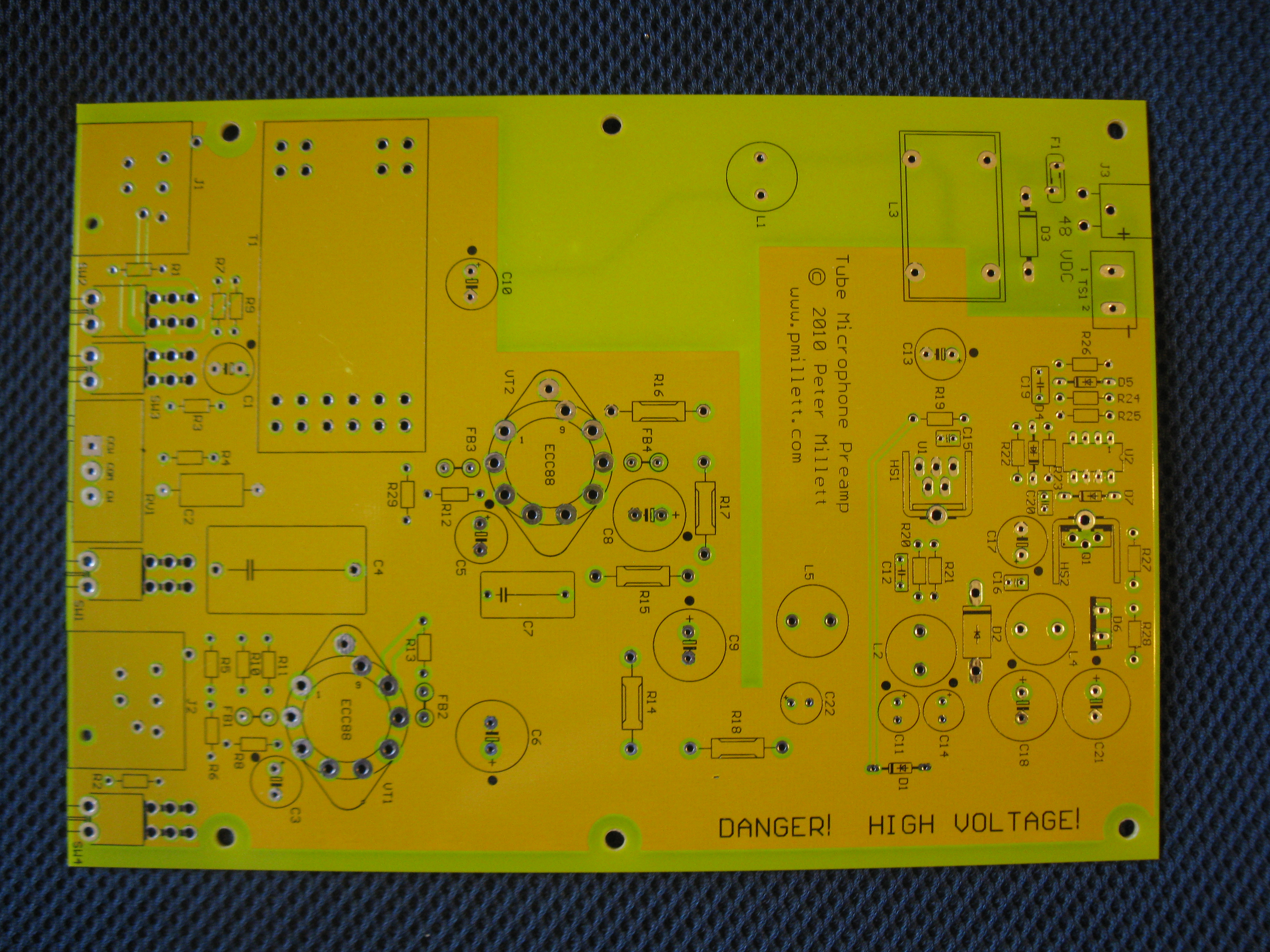
I designed a PCB to contain the amp and fit inside an off-the-shelf enclosure.
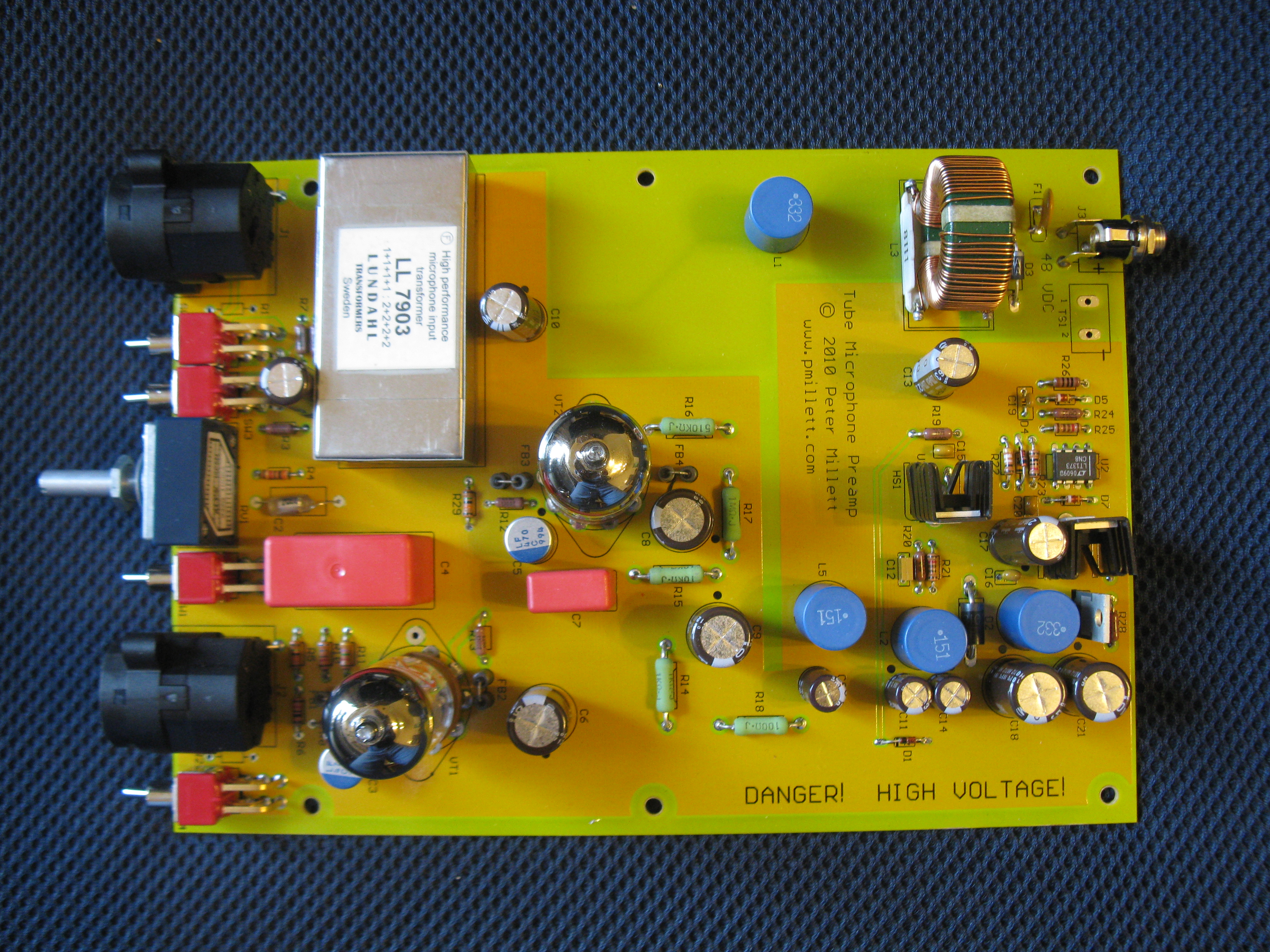
Here's what the PCB looks like (click for a full-size image):
...and the assembled PCB:
The enclosure I put this in is an LMB-Heeger EAS-500 extruded box. I had front and rear panels made by Front Panel Express to fit the box.
You can download a zip file with my FPE front and rear files here.
I'm waiting to get the front and rear panels back from being laser-engraved. When I get them back I'll post photos of the whole thing put together. But really the guts are more interesting anyway :)